Optical image measuring apparatus

Inactive Publication Date: 2005-10-06
KK TOPCON
View PDF5 Cites 35 Cited by
  • Summary
  • Abstract
  • Description
  • Claims
  • Application Information

AI Technical Summary

Benefits of technology

[0030] According to the optical image measuring apparatus of the present invention, the storage time of the photo detection means can be changed and the interference light is detected every changed storage time. Therefore, it is possible to obtain the image of the object to be measured at each depth corresponding to the scanning interval a

Problems solved by technology

Therefore, the measurement of the object to be measured 105 requires a long time.
In addition, it is hard to shorten a measurement time in view of measurement fundamentals.
Therefore, it is supposedly hard to actually use the apparatus in fields that require a high resolution image, such as a medical field and an industrial field.
For example, when precise measurement is unnecess

Method used


Image

  • Optical image measuring apparatus
  • Optical image measuring apparatus
  • Optical image measuring apparatus

Examples


Embodiment Construction

[0037] Hereinafter, an example of an optical image measuring apparatus according to an embodiment of the present invention will be described in detail with reference to the accompanying drawings.

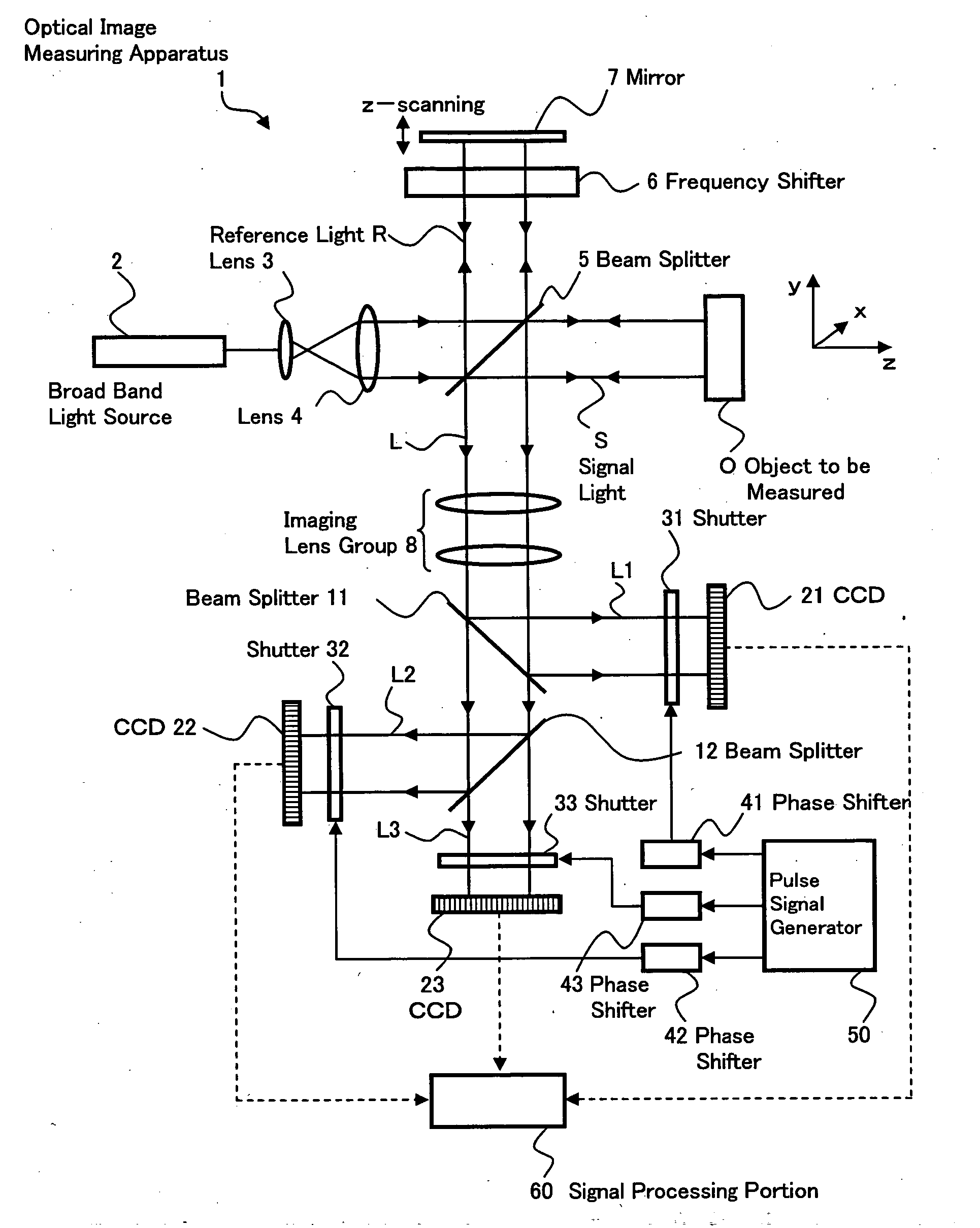
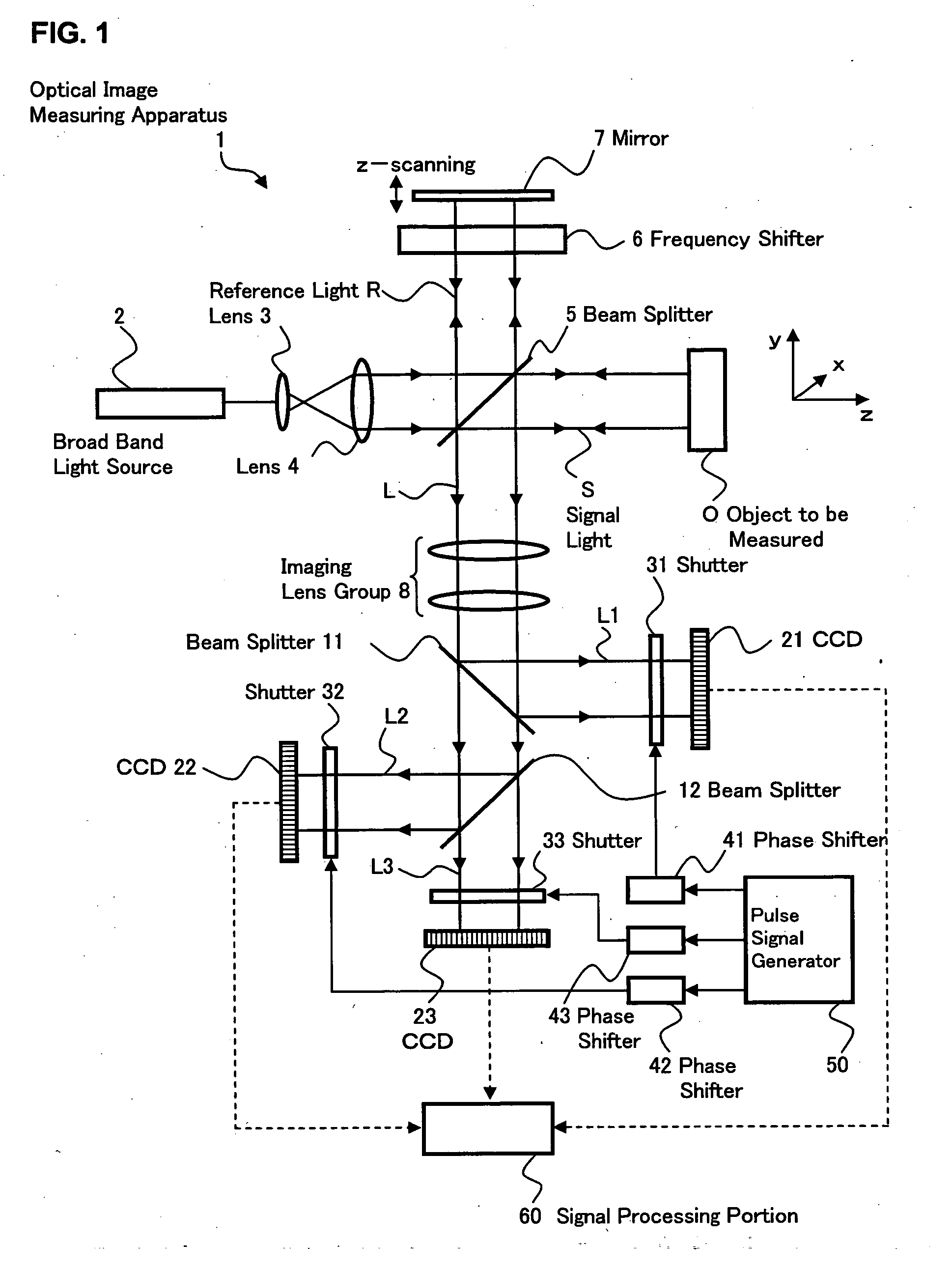
[0038] Hereinafter, an optical image measuring apparatus having a structure for obtaining a signal intensity of interference light and a spatial phase distribution thereof based on heterodyne signals obtained by receiving interference light beams on three optical paths into which an optical path of the interference light is divided will be described as an embodiment of the present invention. Note that it is possible to suitably employ a structure in which the optical path of the interference light is not divided for detection, a structure in which the optical path of the interference light is divided into two for detection, or a structure in which the optical path of the interference light is divided into four or more for detection.

(Structure of Apparatus)

[0039]FIG. 1 shows an example of...


PUM


Abstract

Provided is an optical image measuring apparatus capable of easily changing a scanning interval of an object to be measured in a depth direction with high precision. The apparatus includes an interference optical system for superimposing signal light propagating through the object to be measured on reference light subjected to frequency shift to produce interference light, a reference mirror driving unit for driving a mirror to scan the object to be measured in the depth direction, shutters for sampling interference light beams, CCDs for storing charges for only a predetermined storage time and outputting electrical signals, a control unit for changing the storage time of the CCDs, a signal processing portion for calculating intensities and phases of interference light beams corresponding to each depth of the object to be measured which are successively detected by the CCDs during scanning based on the electrical signals successively outputted from the CCDs every changed storage time, and a setting operation unit for setting the storage time of the CCDs by an operator.

Description

BACKGROUND OF THE INVENTION [0001] 1. Field of the Invention [0002] The present invention relates to an optical image measuring apparatus for applying a light beam to an object to be measured, particularly a light scattering medium and measuring a surface form or inner form of the object to be measured is measured based on a reflected light beam or a transmitted light beam to produce an image of a measured form. In particular, the present invention relates to an optical image measuring apparatus for measuring the surface form or inner form of the object to be measured by using an optical heterodyne detection method to produce the image of the measured form. [0003] 2. Description of the Related Art [0004] In recent years, attention has been given to an optical image measuring technique for producing an image of a surface or inner portion of an object to be measured using a laser light source or the like. This optical image measuring technique is not hazardous to human bodies in contr...

Claims


Application Information

Patent Timeline
IPC IPC(8): A61B3/12G01B11/00A61B5/00G01B9/02G01N21/17G01N21/47G01N21/49
CPCA61B3/102A61B5/0066A61B5/0073G01N21/49G01B2290/45G01B9/02012G01B9/02003G01B9/02091G01N2021/1782
Inventor CHAN, KINPUIAKIBA, MASAHIROFUKUMA, YASUFUMIOTSUKA, HIROYUKITSUKADA, HISASHI
Owner KK TOPCON
Why Eureka
Try Eureka