Eureka AIR delivers breakthrough ideas for toughest innovation challenges, trusted by R&D personnel around the world.

Method and system for admission control in communication networks, related network and computer program product therefor

Active Publication Date: 2005-10-06
STMICROELECTRONICS SRL
View PDF25 Cites 104 Cited by
  • Summary
  • Abstract
  • Description
  • Claims
  • Application Information

AI Technical Summary

Benefits of technology

[0021] The arrangement described herein thus presents a new approach for limiting such effects. A procedure is introduced that runs in the residential gateway (or access point) and keeps track of ongoing transmissions. When new TCP / IP sessions that could deteriorate the quality of the audiovisual stream(s) are detected, the algorithm selectively discards interfering packets. In that way a call admission control function is performed, which does not need specific signaling mechanisms to be introduced in the other terminals of the Wireless LAN, thereby reducing complexity.

Problems solved by technology

However, none of the above-mentioned standards has been developed to support streaming services, which require strict quality of service (QoS) guarantees in terms of delay and delay variation.
The lack of quality of service (QoS) support at the MAC (Medium Access Control) layer of existing WLANs makes audio video streaming particularly sensitive to interfering data traffic.
In practice, however, the attenuation of the signal caused by walls and multipath effects of a closed environment such as a home environment sometimes result in a high (and variable) bit error rate.
Furthermore, as wireless equipment in the 2.4 and 5 GHz ISM bands is becoming commonplace, multiple users may be sharing the same radio spectrum in an uncoordinated way, thereby producing mutual interference.
Firstly, the need of re-transmitting frames causes bandwidth waste.
Secondly, such retransmissions increase the jitter of frames that arrive at the receiver of a real-time flow: a bigger buffer is therefore needed to compensate for the ensuing delay variations.

Method used


Image

  • Method and system for admission control in communication networks, related network and computer program product therefor
  • Method and system for admission control in communication networks, related network and computer program product therefor
  • Method and system for admission control in communication networks, related network and computer program product therefor

Examples


Embodiment Construction

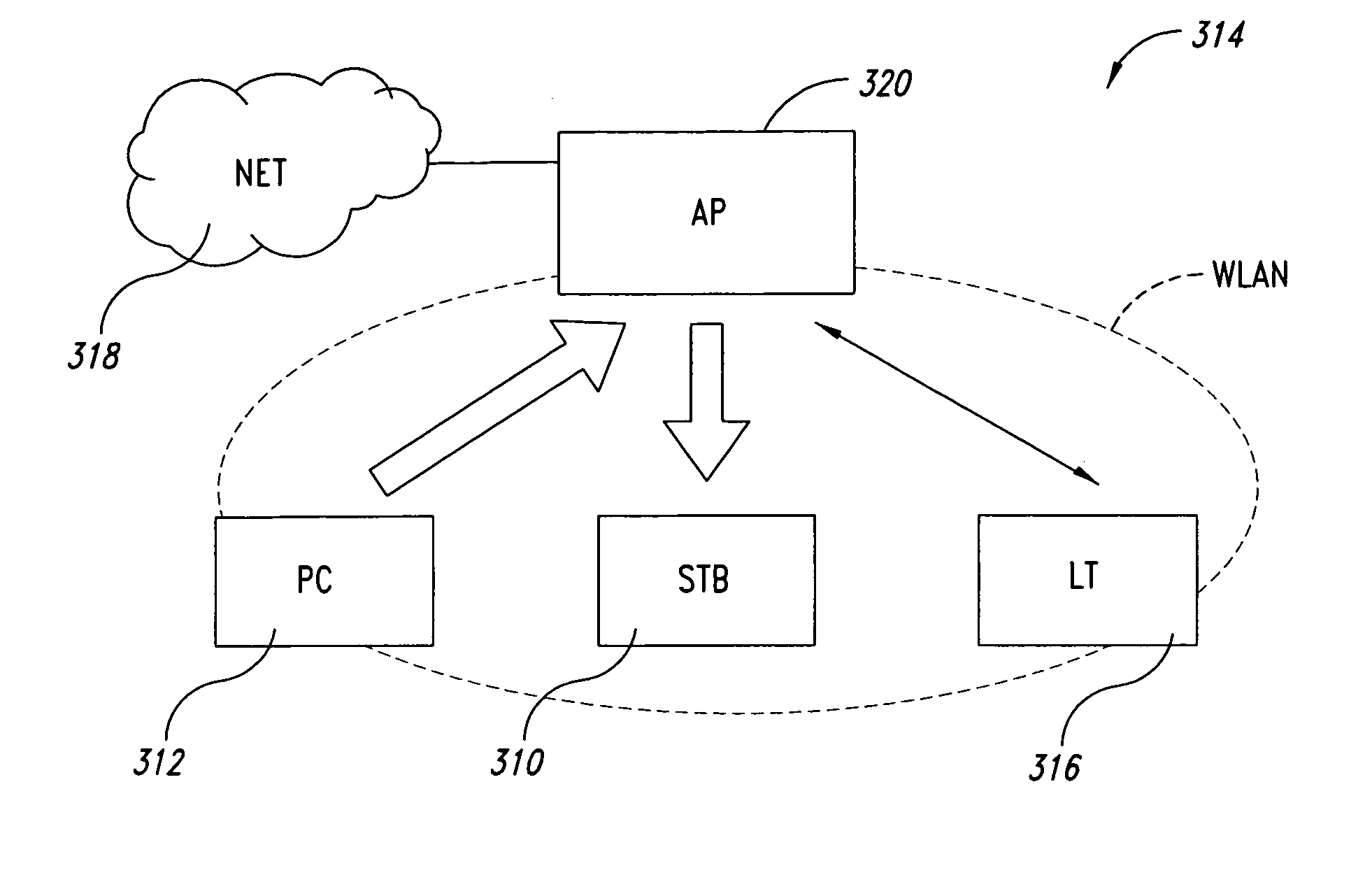
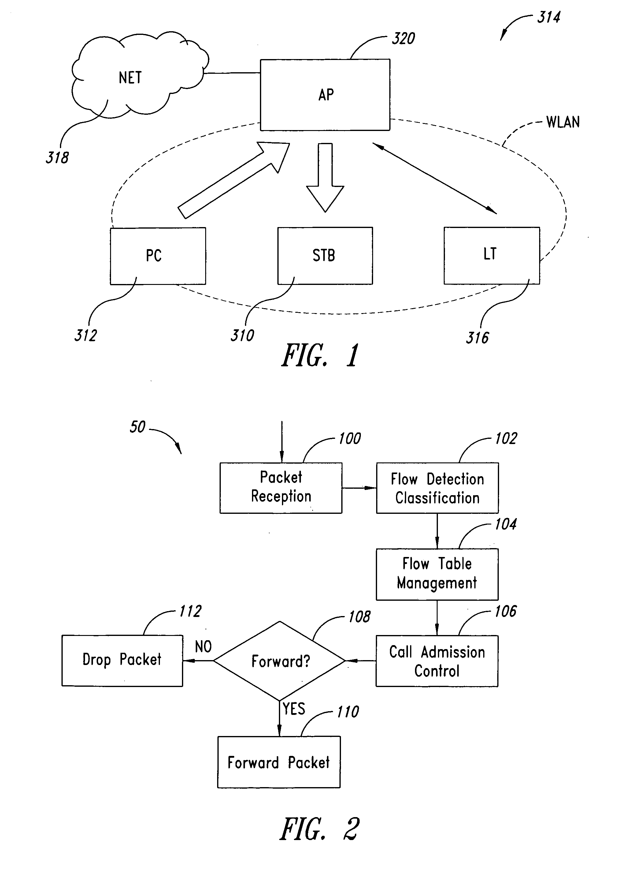
[0036] An exemplary home WLAN networking scenario suitable for use with an embodiment of the invention is depicted in FIG. 1. There, a set-top box STB 310 is shown receiving a stream from a personal computer PC 312 through a Wireless LAN (WLAN) 314. At the same time, a laptop LT 316 is accessing the Internet (NET) 318 through the WLAN 314 access point AP 320, which has a broadband connection.

[0037] In this scenario, the TCP / IP (Transport Control Protocol / Internet Protocol) connection could use a significant portion of the radio bandwidth, especially if the Internet connection is broadband. This situation results in a decrease of the bandwidth available for the real-time stream. In a common case where the video source cannot adapt the source-coding rate to the variable channel capacity, a loss of packets is experienced at the receiver, with an unacceptable video quality. This phenomenon may be burst-like and largely unpredictable.

[0038] For the sake of completeness, it should be me...


PUM


Abstract

A system for admission control in a wireless local area network adapted to serve a set of stations and manage real time transmission as well as and TCP / IP sessions includes an access point (AP) configured for: when either a new station joins the network or a new TCP / IP session is being initiated, checking if sufficient bandwidth is available in the network for the new traffic flow associated with the new station or TCP / IP session without interfering with any ongoing real time transmission in the network, and in case no sufficient bandwidth is found to be available, whereby said new traffic flow could interfere with said ongoing real time transmission, blocking such new traffic flow.

Description

BACKGROUND OF THE INVENTION [0001] 1. Field of the Invention [0002] The present disclosure relates to techniques for admission control in communication networks. In particular, the disclosure pays specific attention to the possible application to local area networks (LANs) such as, e.g., a wireless LAN. [0003] The disclosure is also adapted for use, e.g., in non-wireless networks (such as the Ethernet), other types of wireless networks (UltraWideBand), or mobile telephone networks including terminals equipped with a WLAN interface. [0004] 2. Description of the Related Art [0005] Wireless LANs (WLANs) are becoming increasingly popular not just for data transmission but also for real time streaming applications. [0006] WLANs are being increasingly introduced in domestic environments mainly for sharing access to a broadband Internet connection. IEEE802.11b (see IEEE802.11b standard, “Wireless LAN Medium Access Control (MAC) and Physical Layer (PHY) specifications”, 1999 edition) runnin...

Claims


Application Information

Patent Timeline
IPC IPC(8): H04L12/28H04L29/08
CPCH04W28/065H04W28/24H04W72/1226H04L69/329H04L67/14H04L67/32H04W84/12H04L67/60H04W72/54
Inventor MELPIGNANO, DIEGO
Owner STMICROELECTRONICS SRL
Why Eureka
Eureka Blog
Learn More