Phase comparison circuit and clock recovery circuit

a phase comparison and clock recovery technology, applied in the direction of dc level restoring means or bias distortion correction, transmission monitoring, instruments, etc., can solve the problems of identifying bit errors, detecting error free transmission, and bit errors

Inactive Publication Date: 2005-10-06
FUJITSU LTD
View PDF6 Cites 73 Cited by
  • Summary
  • Abstract
  • Description
  • Claims
  • Application Information

AI Technical Summary

Benefits of technology

[0021] According to the present invention, even when there is a phase difference that exceeds ±π, the phase of the clock signal can be controlled so as to correct the phase difference without occurrence of cycle slip.

Problems solved by technology

In such systems, different from the conventional high-speed optical communication systems, there is a case where an optical receiving circuit receives a signal with a bad SN ratio that may cause a bit error.
However, even when a signal output from the optical receiving circuit includes an error, the error can be corrected by a bit error correcting circuit that is connected after the optical receiving circuit, so that error free transmission can be performed.
However, when the SN ratio of the input data signal is not good, the data signal includes noise in an amplitude direction, so that the phase comparison circuit 3 detects a component of phase noise that is converted from the noise.
As a result, the phase of the clock signal is controlled to an excessive degree so that problems such as increase of identifying bit errors, increase of jitter of the clock signal, and further, PLL unlock may occur.
As mentioned above, according to the conventional technology, there is a problem in that not only a phase noise component of the data signal is detected but also a noise component in the amplitude direction may be detected as phase noise.
Related to this problem, there is a problem in that when a large phase difference that exceeds ±π occurs, a cycle slip occurs in the PLL circuit so that unlock of the PLL circuit occurs.
However, when a large phase difference that exceeds ±π occurs, the cycle slip occurs since the PLL circuit operates to control the phase of the clock signal to φ=±2π, so that the unlock of the PLL circuit occurs.

Method used


Image

  • Phase comparison circuit and clock recovery circuit
  • Phase comparison circuit and clock recovery circuit
  • Phase comparison circuit and clock recovery circuit

Examples


first embodiment

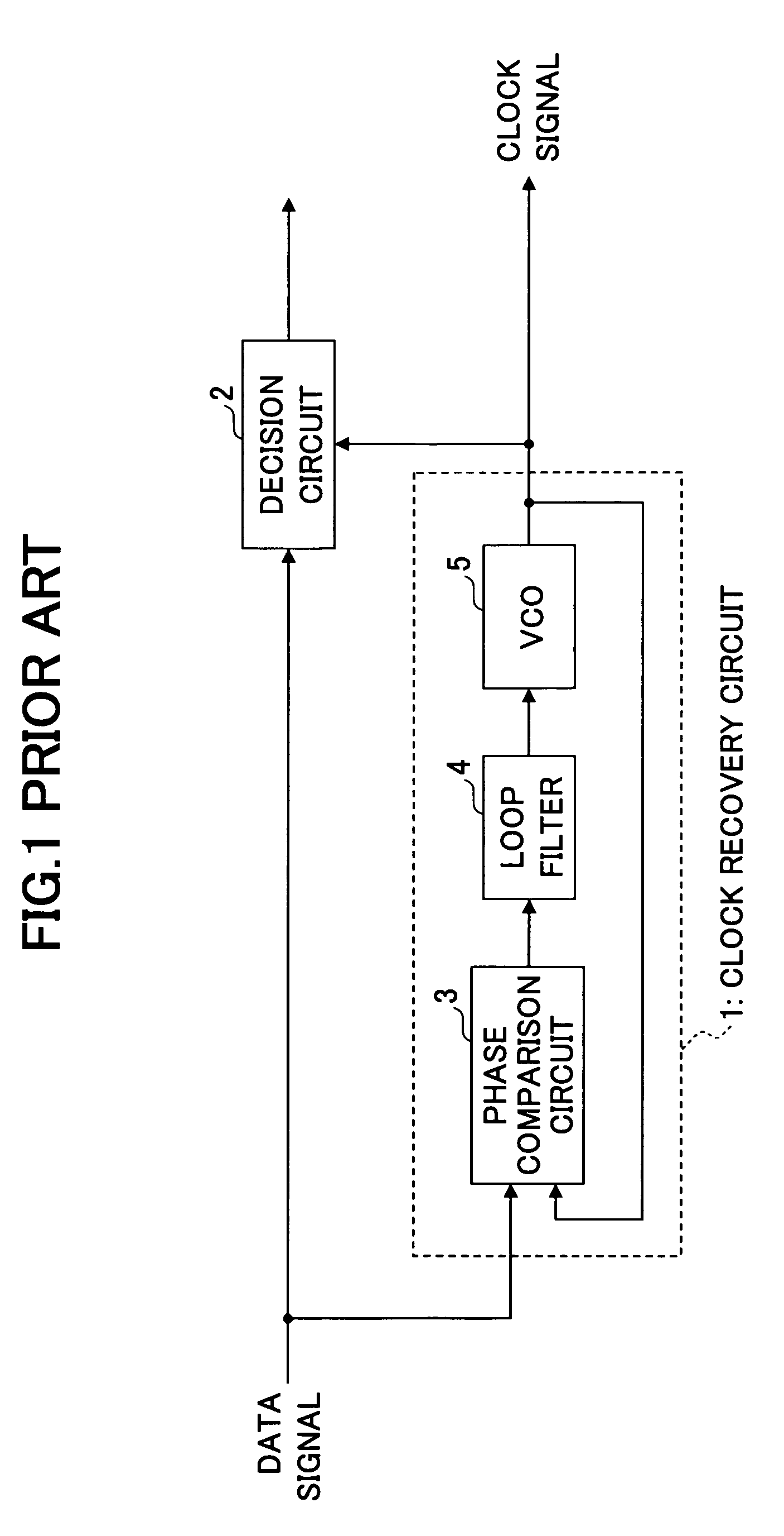
[0052] A first embodiment based on the above-mentioned principle is described. FIG. 6 shows a configuration of a phase comparison circuit in the first embodiment.

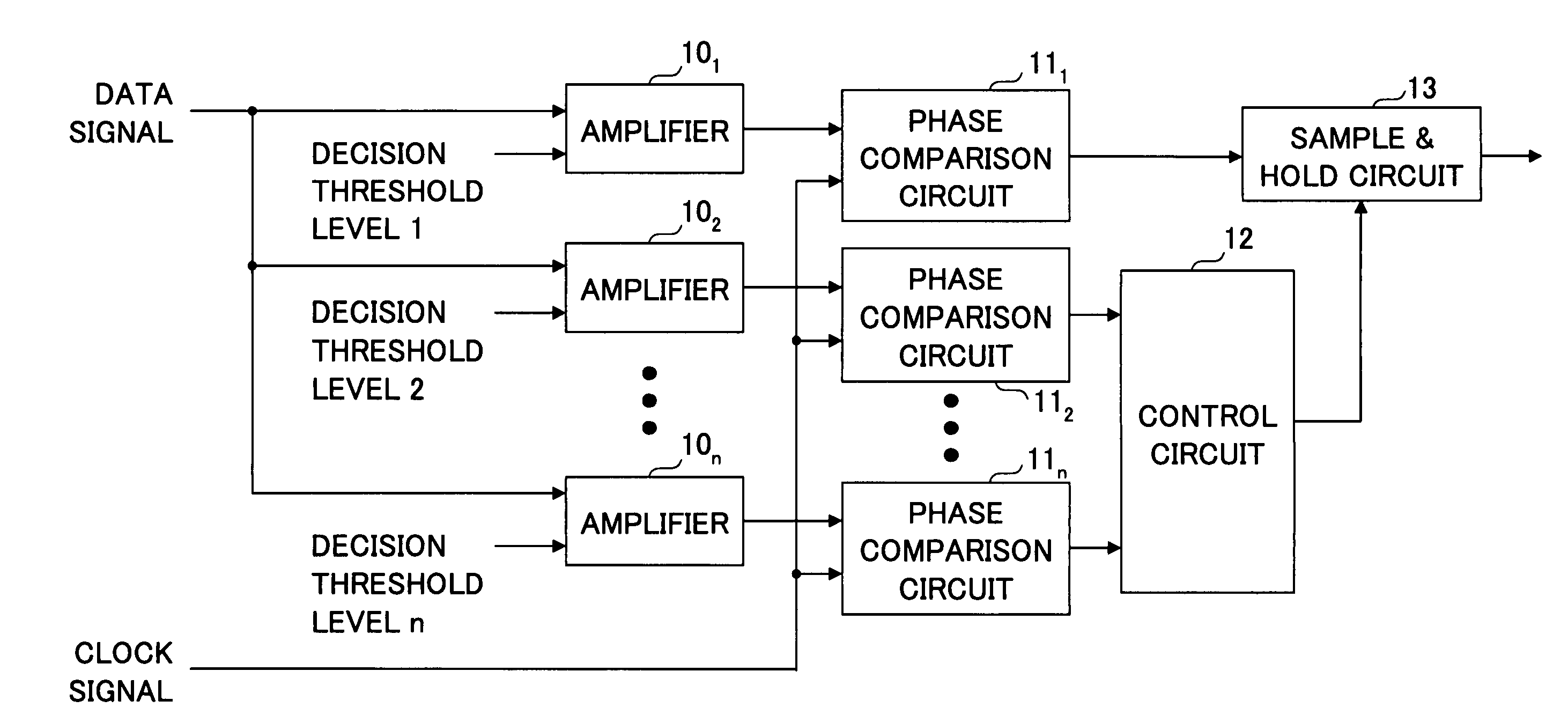
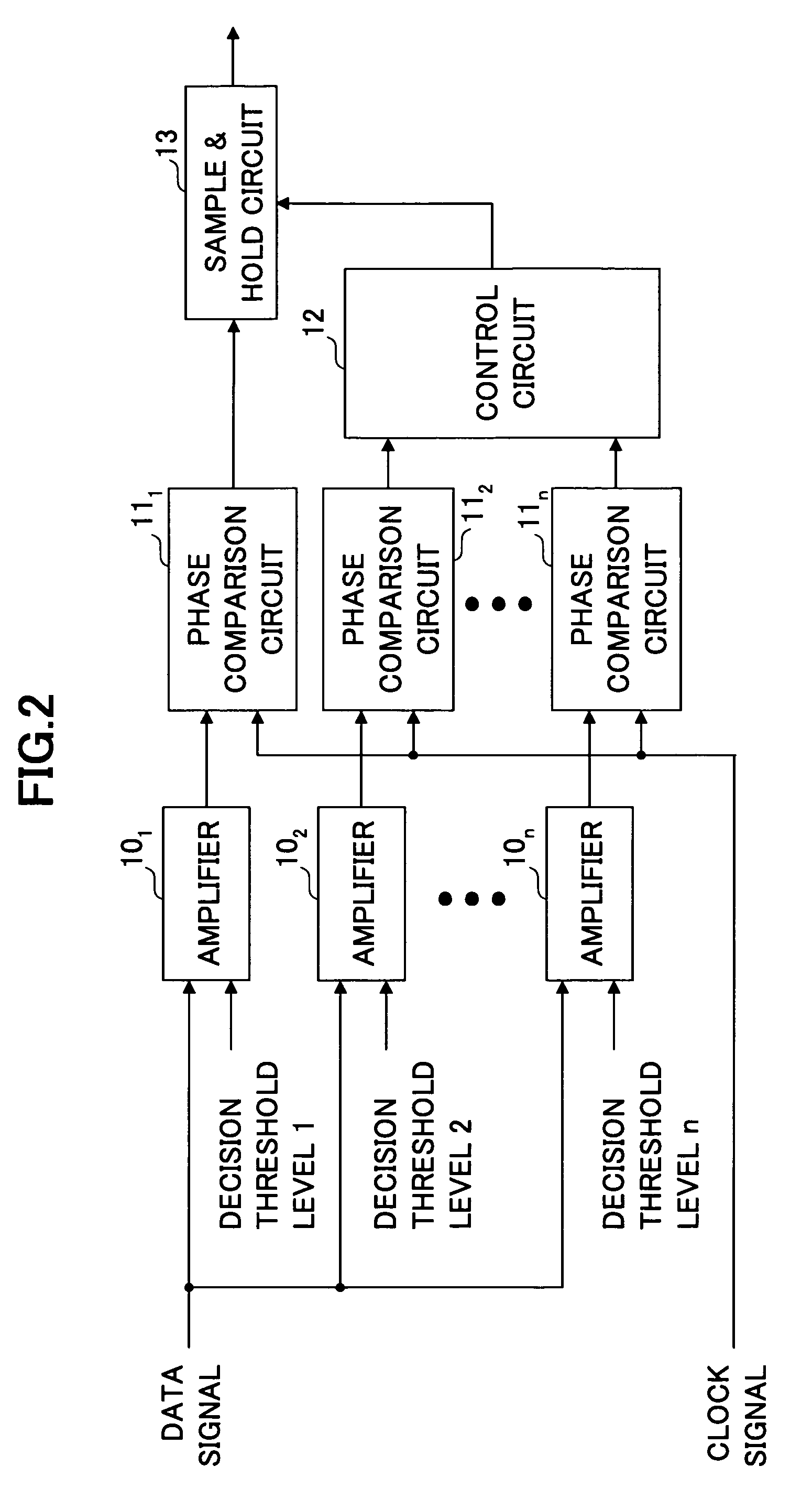
[0053] The phase comparison circuit in the first embodiment includes amplifiers 201˜203, phase comparison circuits 211˜213 each for comparing phases of a signal from a corresponding amplifier and the clock signal, a circuit 22 for calculating a difference between a phase difference φ2 from the phase comparison circuit 211 and a phase difference φ3 from the phase comparison circuit 213, a comparator 23 for comparing a reference value Δφ min with an output value from the circuit 22, and a sample-and-hold circuit 24 for holding and outputting a signal from the phase comparison circuit 211. The circuit 22 and the comparator 23 correspond to the control circuit 12.

[0054] As shown in the figure, a decision threshold level Vth is supplied to the amplifier 201, a decision threshold level Vth+dV is supplied to the amplifier 202, a...

second embodiment

[0055] Next, a second embodiment is described. FIG. 7 shows a configuration of a phase comparison circuit in the second embodiment.

[0056] The phase comparison circuit in the second embodiment includes amplifiers 301˜302, phase comparison circuits 311˜312 each for comparing phases of a signal from an amplifier and the clock signal, a circuit 32 for calculating a difference between a phase difference φ1 from the phase comparison circuit 31, and a phase difference φ2 from the phase comparison circuit 312, a comparator 33 for comparing a reference value Δφ min with an output value from the circuit 32, and a sample-and-hold circuit 34 for holding and outputting a signal from the phase comparison circuit 311. The circuit 32 and the comparator 33 correspond to the control circuit 12 of FIG. 2.

[0057] As shown in the figure, a decision threshold level Vth is supplied to the amplifier 301, and a decision threshold level Vth+dV is supplied to the amplifier 302. Each phase comparison circuit ...

third embodiment

[0059] Next, a third embodiment is described. FIG. 8 shows a configuration of a phase comparison circuit in the third embodiment.

[0060] The phase comparison circuit in the third embodiment includes amplifiers 401˜402, an oscillator 42 for periodically changing a decision threshold level of the amplifier 402, an adder 43 for adding a signal of the oscillator 42 and a signal indicating the decision threshold level, phase comparison circuits 441˜442 each for comparing phases of a signal from an amplifier and the clock signal, a circuit 45 for calculating a difference between a maximum value and a minimum value of an output φ2 from the phase comparison circuit 442, a comparator 46 for comparing a reference value Δφ min with an output value from the circuit 45, and a sample-and-hold circuit 47 for holding and outputting a signal from the phase comparison circuit 441. The circuit 45 and the comparator 46 correspond to the control circuit 12 of FIG. 2.

[0061] As shown in the figure, a dec...


PUM


Abstract

A phase comparison circuit for outputting a phase difference signal indicating a phase difference between a data signal and a clock signal is disclosed. The disclosed phase comparison circuit includes: a detection part for outputting a plurality of signals indicating phases of the data signal according to different decision threshold levels; a phase comparison part for outputting phase difference signals each indicating a phase difference between a signal in the plurality of signals output from the detection part and the clock signal; and a control part for determining whether to output a particular phase difference signal in the phase difference signals by using the whole or a part of the phase deference signals.

Description

CROSS-REFERENCE TO RELATED APPLICATION [0001] This application is a U.S. continuation application filed under 35 USC 111(a) claiming benefit under 35 USC 120 and 365(c) of PCT application JP03 / 04118, filed Mar. 31, 2003. The foregoing application is hereby incorporated by reference.BACKGROUND OF THE INVENTION [0002] 1. Field of the Invention [0003] The present invention relates to a clock recovery circuit and a phase comparison circuit that is used in the clock recovery circuit. More particularly, the present invention relates to the clock recovery circuit and the phase comparison circuit that can extract a phase-stable clock signal for an input data signal even when a SN (signal-to-noise) ratio of the input data signal is bad. [0004] 2. Description of the Related Art [0005] In a conventional high-speed optical communication system, an optical receiving circuit receives a signal having a good SN ratio that does not cause any bit error in transmitted data. In recent years and continu...

Claims


Application Information

Patent Timeline
Patent Type & Authority Applications(United States)
IPC IPC(8): G01S1/00H03K5/26H03L7/08H03L7/085H03L7/087H03L7/091H04L7/02H04L7/033H04L25/06H04L25/40
CPCG01S1/00H03L7/085H04L25/061H03L7/091H04L7/033H03L7/087
Inventor KUWATA, NAOKI
Owner FUJITSU LTD
Why Eureka
Try Eureka