Nonaqueous electrolyte secondary battery

a secondary battery and non-aqueous electrolyte technology, applied in the direction of batteries, sustainable manufacturing/processing, cell components, etc., can solve the problems of affecting the performance of the secondary battery, etc., to achieve the effect of high safety

Inactive Publication Date: 2005-10-06
KK TOSHIBA
View PDF9 Cites 93 Cited by
  • Summary
  • Abstract
  • Description
  • Claims
  • Application Information

AI Technical Summary

Benefits of technology

[0012] An object of the present invention is to provide a nonaqueous electrolyte secondary battery having a high safety.

Problems solved by technology

In general, the nonaqueous electrolyte secondary battery, if over-charged, is accompanied by dangers such as temperature elevation, liquid leakage, gas release, and ignition.
However, the outer element, which is detachable, lacks safety and gives rise to, for example, cost elevation and, thus, the outer element is not desirable.
Also, the element of the temperature-dependent type was defective in that the operation thereof tended to be nonuniform.
However, in the case of employing the pressure-dependent type inner element, which is operated by the elevation of the internal pressure, it is impossible to use a flexible case made of a flexible material such as a laminate film.
However, the operation of the expansion-dependent type inner element is made nonuniform by the size of the free space around the nonaqueous electrolyte secondary battery.
It should be noted in particular that, where the free space around the nonaqueous electrolyte secondary battery is extremely small, the inner element is unlikely to be expanded, with the result that the safety of the nonaqueous electrolyte secondary battery is impaired.
However, the nonaqueous electrolyte secondary battery disclosed in the patent document quoted above gives rise to the problem that, if the cross sectional area of the positive electrode terminal is increased in an attempt to improve the high rate characteristics of the battery, the positive electrode terminal is rendered unlikely to be alloyed so as to impair the safety of the battery.
Also, if the cross sectional area of the positive electrode terminal is decreased in an attempt to promote the alloying of the positive electrode terminal, an additional problem is generated that the high rate characteristics of the nonaqueous electrolyte secondary battery are lowered.

Method used


Image

  • Nonaqueous electrolyte secondary battery
  • Nonaqueous electrolyte secondary battery
  • Nonaqueous electrolyte secondary battery

Examples


first embodiment

[0132] A nonaqueous electrolyte secondary battery comprising a wound type electrode group will now be described. In the nonaqueous electrolyte secondary battery described in the following, a thermally shrinkable resin tape is used for convenience as the stress imparting member for imparting a tensile stress or a shearing stress.

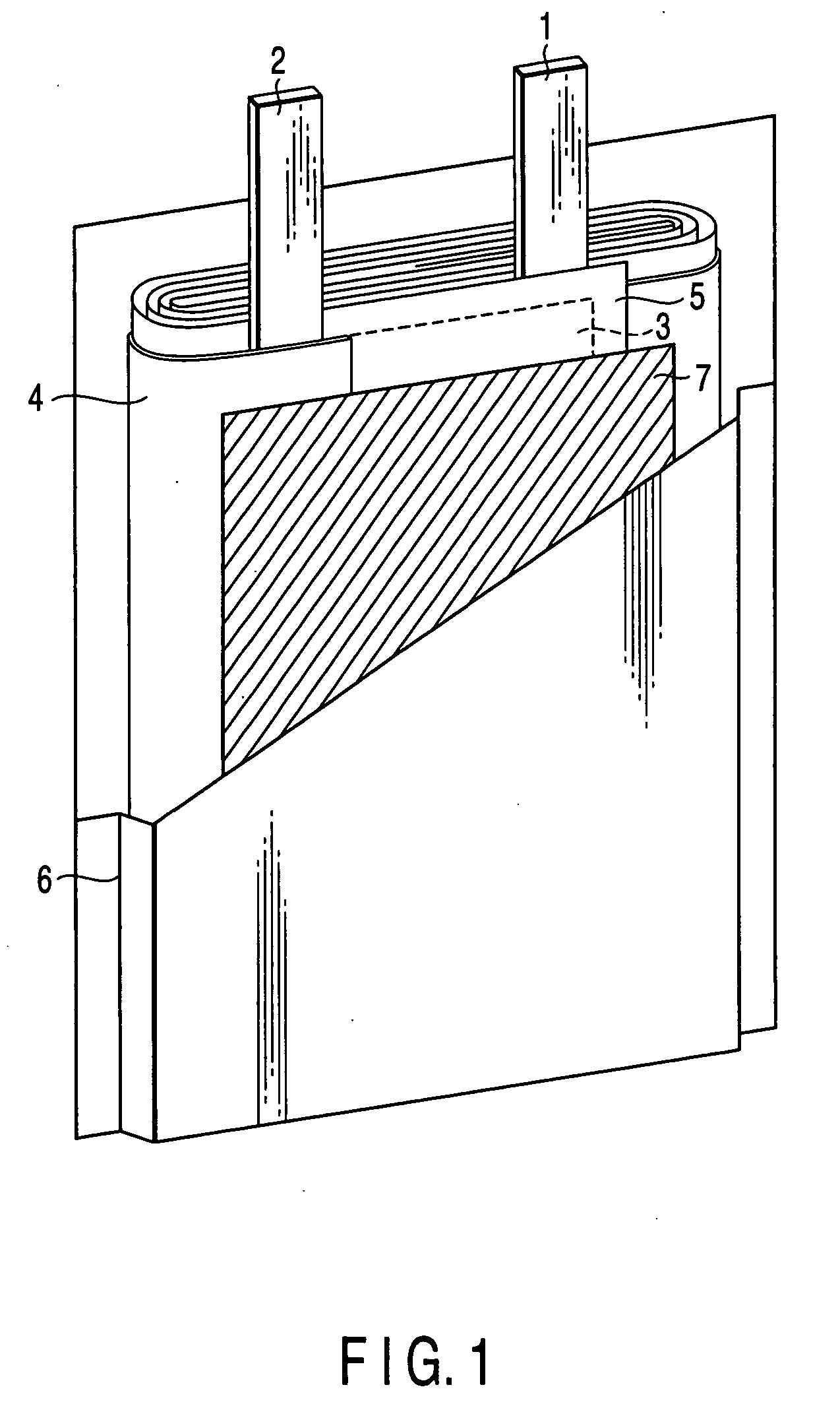
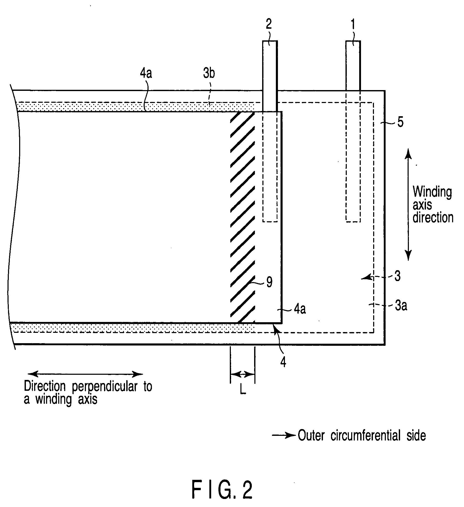
[0133]FIG. 1 is an oblique view, partly broken away, schematically showing the construction of a nonaqueous electrolyte secondary battery, which comprises a wound type electrode group, according to the first embodiment of the present invention. As shown in FIG. 1, the electrode group is prepared by spirally winding a laminate structure including a positive electrode 3, a negative electrode 4 and a separator 5 interposed between the positive electrode 3 and the negative electrode 4. The laminate structure noted above is spirally wound such that the negative electrode 4 is positioned to constitute the outermost layer of the laminate structure and that the woun...

second embodiment

[0148] A nonaqueous electrolyte secondary battery comprising a laminate type electrode group will now be described. In this embodiment, the stress imparting member for imparting a tensile stress or a shearing stress is formed of a spring, for convenience.

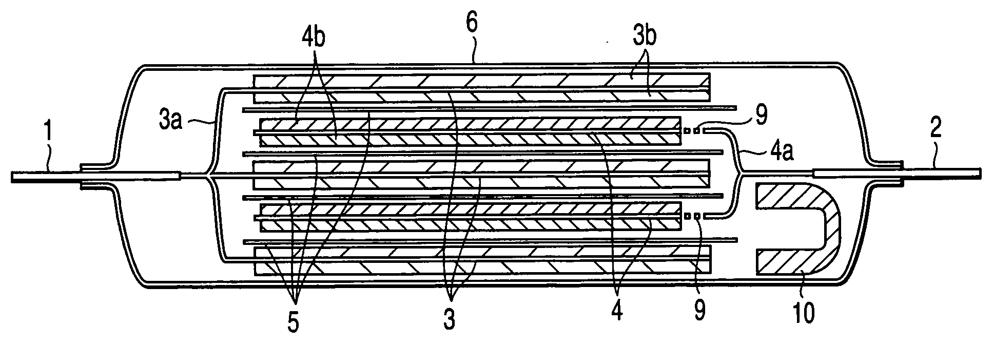
[0149]FIG. 6 is a plan view schematically showing the construction of one of the electrode groups included in a laminate type nonaqueous electrolyte secondary battery according to a second embodiment of the present invention. FIG. 7 is a cross sectional view schematically showing the construction of the laminate type nonaqueous electrolyte secondary battery comprising electrode group shown in FIG. 6. Shown in this drawing is the battery under the state before operation of the current stopping mechanism. For convenience, the portion concealed by the upper layer is denoted by dotted lines. As shown in FIG. 6, the positive electrode 3 having an area smaller than that of the separator 5 is arranged on one surface (back surface in FIG. ...

example 1

[0160] A slurry was prepared by dispersing lithium-cobalt oxide (LiCoO2) used as a positive electrode active material, a graphite power used as a conductive agent, and polyvinylidene fluoride (PVdF) used as a binder in an n-methylpyrrolidone (NMP) used as a solvent in a weight ratio of 87:8:5. Then, an aluminum foil having a thickness of 15 μm and a purity of 99.99% was coated with the slurry thus prepared, followed by drying and, then, pressing the aluminum foil coated with slurry so as to obtain an oblong positive electrode sized at 51 mm×470 mm and having an electrode density of 3.5 g / cm3.

[0161] On the other hand, another slurry was prepared by dispersing lithium titanate (Li4Ti5O12) having an average particle diameter of 0.5 μm, which was used as a negative electrode active material, a carbon powder having an average particle diameter of 0.4 μm, which was used as a conductive agent, and PVdF used as a binder in an n-methylpyrrolidone (NMP) solvent in a weight ratio of 90:7:3. T...


PUM

PropertyMeasurementUnit
lithium electrode potentialaaaaaaaaaa
operating temperatureaaaaaaaaaa

Abstract

A nonaqueous electrolyte secondary battery includes a negative electrode including a negative electrode current collector and a negative electrode active material layer that is formed on a first region of the negative electrode current collector, a negative electrode terminal connected to an edge section of a second region of the negative electrode current collector, a positive electrode including a positive electrode active material layer positioned to face the negative electrode active material layer and the second region, and a stress imparting member which imparts a tensile stress or a shearing stress to the second region.

Description

CROSS-REFERENCE TO RELATED APPLICATIONS [0001] This application is based upon and claims the benefit of priority from prior Japanese Patent Application No. 2004-094984, filed Mar. 29, 2004, the entire contents of which are incorporated herein by reference. BACKGROUND OF THE INVENTION [0002] 1. Field of the Invention [0003] The present invention relates to a nonaqueous electrolyte secondary battery. [0004] 2. Description of the Related Art [0005] Much research is being carried out on a nonaqueous electrolyte secondary battery that is charged and discharged by the migration of lithium ions between the positive electrode and the negative electrode in an attempt to develop a battery having a high energy density. [0006] In general, the nonaqueous electrolyte secondary battery, if over-charged, is accompanied by dangers such as temperature elevation, liquid leakage, gas release, and ignition. Therefore, a safety mechanism for decreasing or stopping the current is mounted to the nonaqueous...

Claims


Application Information

Patent Timeline
Patent Type & Authority Applications(United States)
IPC IPC(8): H01M4/13H01M4/66H01M10/04H01M10/05H01M10/052H01M10/058H01M10/0585H01M10/0587H01M50/574H01M50/595
CPCH01M2/263H01M2/34H01M2/345H01M4/13H01M4/661H01M10/052H01M10/0587H01M2004/021Y02E60/10H01M50/578Y02P70/50H01M50/595H01M50/574H01M10/4235H01M4/662H01M2200/10H01M50/572H01M50/538H01M50/119
Inventor TATEBAYASHI, YOSHINAOINAGAKI, HIROKITAKAMI, NORIO
Owner KK TOSHIBA
Why Eureka
Try Eureka