
Semiconductor device with shallow trench isolation and method of fabricating the same

a technology of semiconductor devices and trenches, applied in semiconductor devices, electrical devices, transistors, etc., can solve the problems of difficult inability to improve precision of conventional fabrication steps, and inability to achieve control performance in the control of etching amount, etc., to achieve stable device characteristics and improve control performance. effect of etching amoun

Inactive Publication Date: 2005-10-06
KK TOSHIBA
View PDF4 Cites 4 Cited by
  • Summary
  • Abstract
  • Description
  • Claims
  • Application Information

AI Technical Summary

Benefits of technology

[0013] Therefore, an object of the present invention is to provide a semiconductor device in which control performance in the control of an amount of etching can be improved when etching is performed for an insulating film buried in a trench formed in the semiconductor substrate, whereupon a stable device characteristic can be obtained, and a method of fabricating the semiconductor device.

Problems solved by technology

However, a conventional fabricating step involves factors which cannot improve the precision in the following points. FIGS. 6A to 6E illustrate typical sectional structures of a semiconductor device according to a conventional fabricating method.
However, the foregoing conventional techniques have the following defects.
As a result, when the silicon oxide film 6 is etched by the solution of BHF, an amount of etching is difficult to control, whereupon the height from the surface of the silicon substrate 1 becomes non-uniform.
This results in an increase in the write time in the characteristic of the device, which increase is undesirable in the practical use.

Method used


Image

  • Semiconductor device with shallow trench isolation and method of fabricating the same
  • Semiconductor device with shallow trench isolation and method of fabricating the same
  • Semiconductor device with shallow trench isolation and method of fabricating the same

Examples


Embodiment Construction

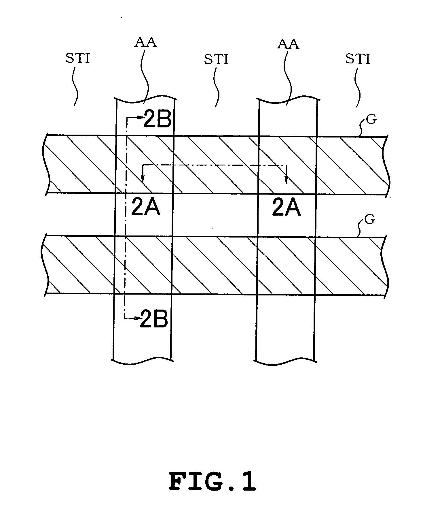
[0023] A first embodiment of the present invention will be described with reference to FIGS. 1 to 4E. The invention is applied to a non-volatile memory such as a flash memory in the first embodiment.

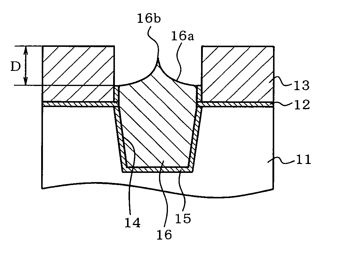
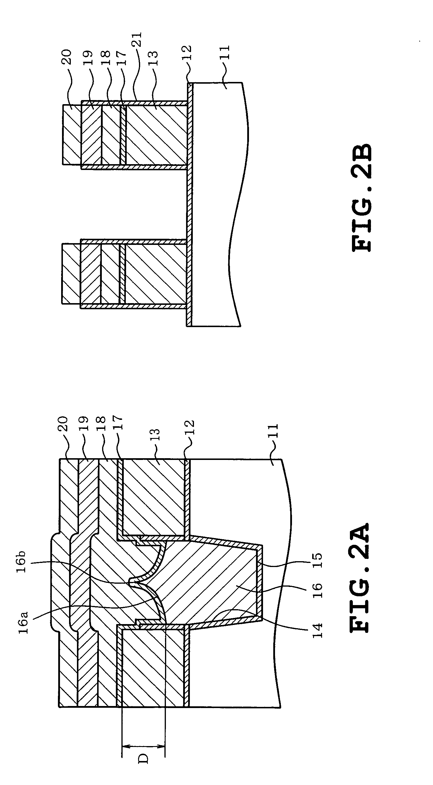
[0024] Referring to FIGS. 2A and 2B, a first silicon oxide film 12 (first insulating film) serving as a gate oxide film is formed on a surface of a silicon substrate 11 serving as a semiconductor substrate. The first silicon oxide film 12 has a film thickness of 8 nm. A first polycrystalline silicon film 13 doped with phosphor is formed on the first silicon oxide film 12. The first polycrystalline silicon film 13 serves as a floating gate and has a film thickness of 165 nm.

[0025] A trench 14 is formed in the silicon substrate 11, the first silicon oxide film 12 and the first polycrystalline silicon film 13 so as to have a predetermined depth in the silicon substrate. A second silicon oxide film 15 with a film thickness of 6 nm is formed on a bottom and both sidewalls of the trench 14 s...


PUM


Abstract

A semiconductor device includes a semiconductor substrate having an upper surface, a trench formed in the semiconductor substrate, a first insulating film formed on the semiconductor substrate so as to be located at opposite sides of the trench, a polycrystalline silicon film stacked on the first insulating film, the polycrystalline silicon film having an upper surface, a second insulating film buried in the trench and having an upper surface end located lower than the upper surface of the polycrystalline silicon film and higher than the upper surface of the semiconductor substrate, the second insulating film having a central upper surface located nearer to the upper surface of the polycrystalline silicon film than the upper surface end thereof.

Description

CROSS-REFERENCE TO RELATED APPLICATION [0001] This application claims priority to Japanese patent application No. 2004-43363, filed Feb. 19, 2004, the content of which is incorporated herein by reference. BACKGROUND OF THE INVENTION [0002] 1. Field of the Invention [0003] The present invention relates to a semiconductor device in which trenches are formed in a semiconductor substrate and an insulator is buried in the trenches so that an element isolation region is formed and a method of fabricating such a semiconductor device. [0004] 2. Description of the Related Art [0005] The semiconductor device of the above-described type includes non-volatile memories such as flash memories. In the non-volatile memories, an etching process requires high precision in a step of forming an element isolation region in a memory cell forming area. However, a conventional fabricating step involves factors which cannot improve the precision in the following points. FIGS. 6A to 6E illustrate typical sec...

Claims


Application Information

Patent Timeline
Patent Type & Authority Applications(United States)
IPC IPC(8): H01L21/762H01L21/8247H01L21/76H01L27/115H01L29/00H01L29/788H01L29/792
CPCH01L21/76224H01L27/115H01L27/11521H10B69/00H10B41/30
Inventor KAMO, RYUICHIWATANOBE, HISASHIIGUCHI, TADASHI
Owner KK TOSHIBA
Learn More