
Semiconductor laser device and method for manufacturing the same

a laser device and semiconductor technology, applied in semiconductor lasers, laser details, electrical equipment, etc., can solve the problems of heat generation, poor reliability, significant losses, etc., and achieve the effect of stable device characteristics and high reliability

Inactive Publication Date: 2007-10-04
PANASONIC CORP
View PDF3 Cites 7 Cited by
  • Summary
  • Abstract
  • Description
  • Claims
  • Application Information

AI Technical Summary

Benefits of technology

[0019] Therefore, with the foregoing in mind, it is an object of the present invention to provide a semiconductor laser device that has an end face window structure in which a refractive index difference between the gain portion and the end face window structure region is suppressed, and that can achieve stable device characteristics and high reliability even in a high output operation.
[0020] It is also an object of the present invention to provide a method for manufacturing a semiconductor laser device that can form an end face window structure with a smaller refractive index variation, suppress a reduction in resistance, and control Zn diffusion in the resonator direction.

Problems solved by technology

However, the above structure for hither output of the laser beam poses the following problems.
This results in significant losses and poor reliability because of increases in a threshold value and an operation current or the generation of regions with a small band gap difference.
(2) Low resistance caused by high-concentration Zn diffusion Since the Zn concentration is higher than the laser gain region, a current flows easily into the end face portion during current injection, which leads to heat generation.
Thus, the band gap becomes smaller, and end face damage is likely to occur.
This may cause a difference in the divergence angle of a laser between the gain portion and the exit end face or a light loss.
However, even if both the methods of JP 2004-259943 A and JP 2001-94206 A are used, it is difficult to avoid the problem (3) of a refractive index difference between the gain portion and the end face window structure region.

Method used


Image

  • Semiconductor laser device and method for manufacturing the same
  • Semiconductor laser device and method for manufacturing the same
  • Semiconductor laser device and method for manufacturing the same

Examples


Embodiment Construction

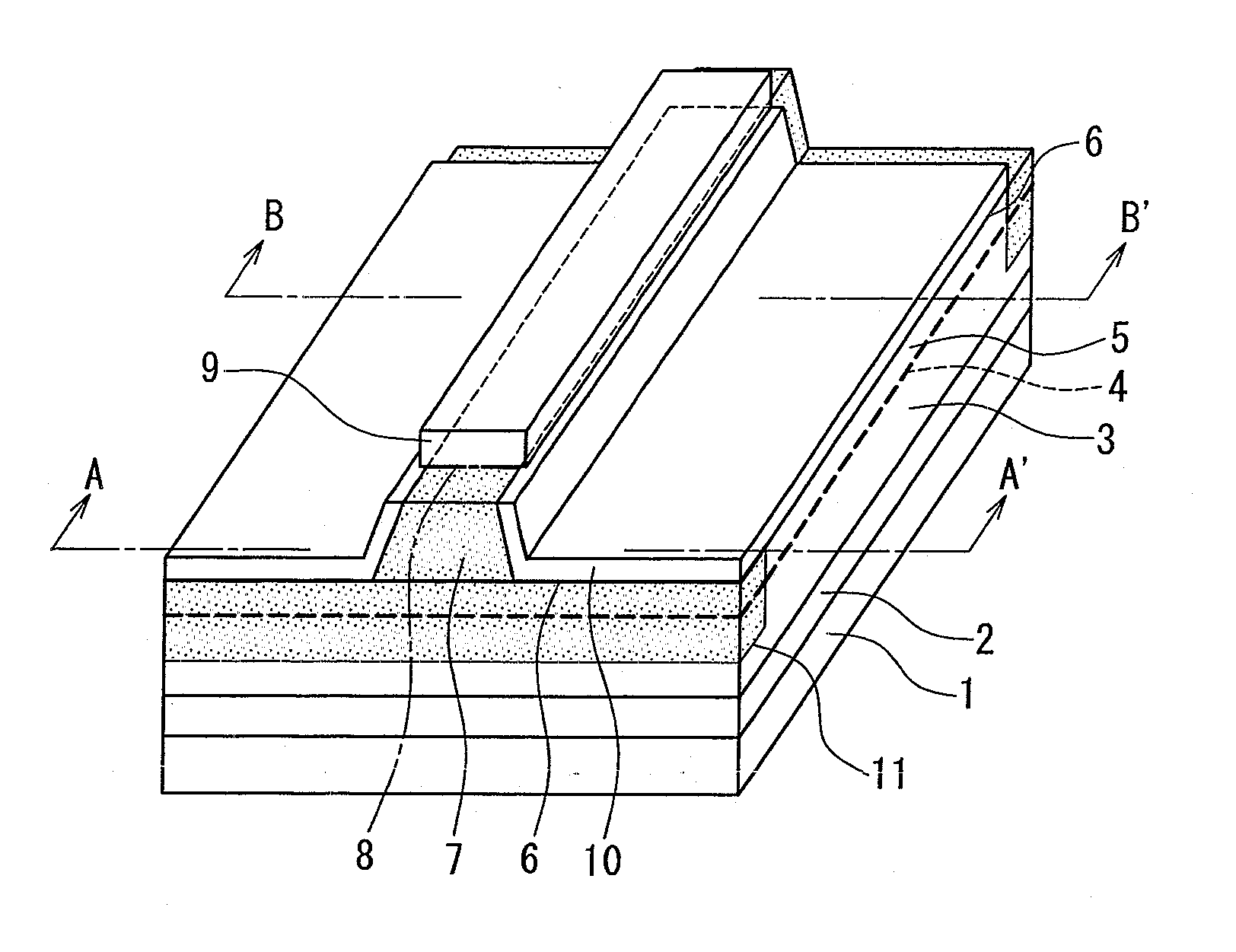
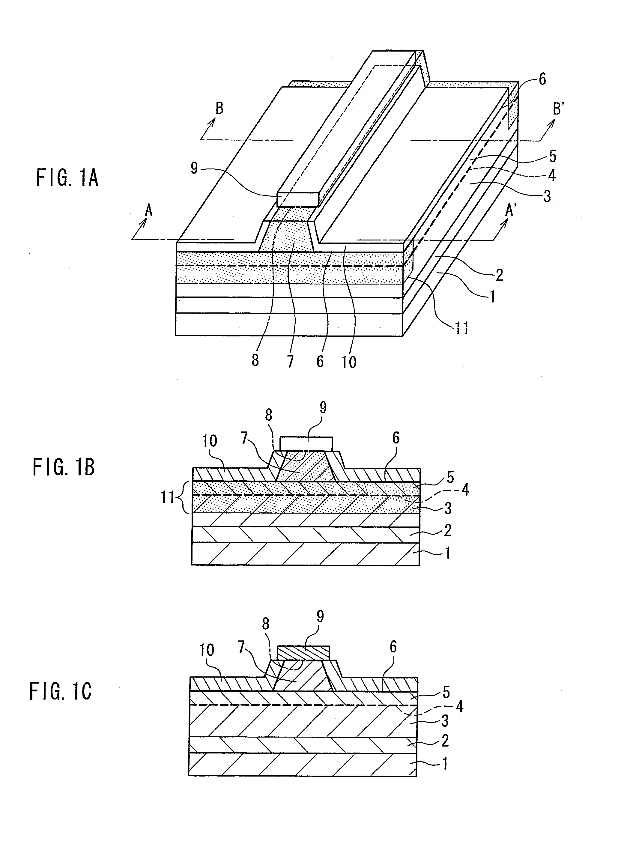
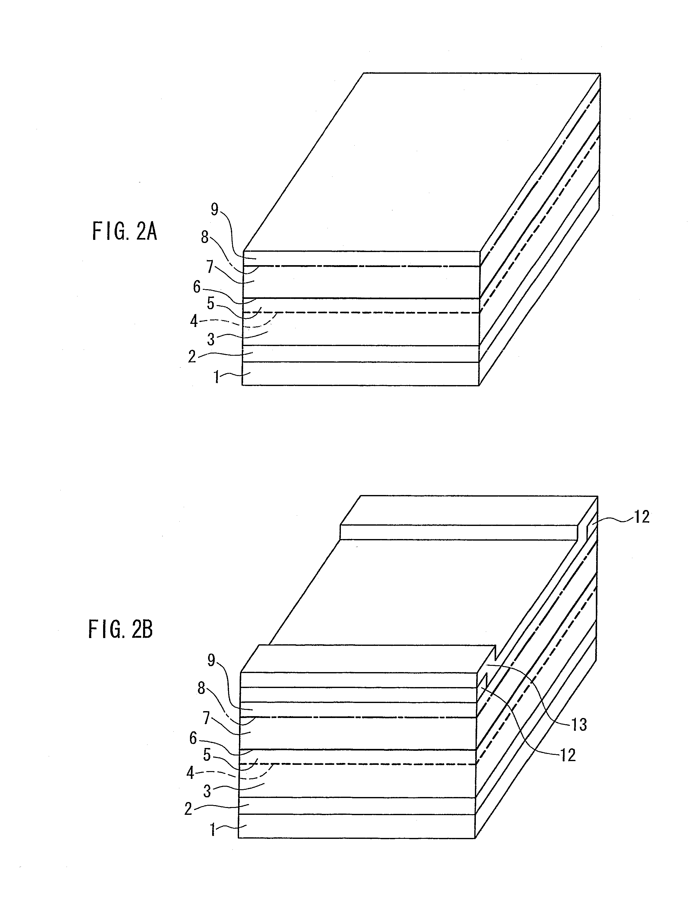
[0034] A semiconductor laser device of the present invention includes a laminated structure of a first conductivity type cladding layer, an active layer having a multiple quantum well structure, and a second conductivity type first cladding layer, a second conductivity type second cladding layer that forms a ridge waveguide, and a second conductivity type contact layer disposed on the second cladding layer. The semiconductor laser device also has an end face window structure in which impurities are diffused into an active layer region of an end face portion in a resonator direction, and thus a band gap is enlarged compared to a gain region that is a portion other than the end face portion. In the second conductivity type first and second cladding layer, the impurity concentration in the gain region is adjusted to be the same as or larger than that in a region of the end face window structure. With this configuration, there is a small difference in refractive index between the gain p...


PUM


Abstract

A semiconductor laser device including the following: a first conductivity type semiconductor substrate; a first conductivity type cladding layer disposed on the semiconductor substrate; an active layer disposed on the first conductivity type cladding layer; a second conductivity type first cladding layer disposed on the active layer; a second conductivity type second cladding layer that is disposed on the second conductivity type first cladding layer and forms a ridge waveguide extending in a resonator direction; a second conductivity type contact layer disposed on the second conductivity type second cladding layer; and an end face window structure in which impurities are diffused into an active layer region of an end face portion in the resonator direction. Thus a band gap is enlarged compared to a gain region that is a portion other than the end face portion. In the second conductivity type first and second cladding layers, an impurity concentration in the gain region is the same as or larger than that in a region of the end face window structure. This configuration can form an end face window structure with a smaller refractive index variation, achieve a higher resistance than a conventional window structure, and control Zn diffusion in the resonator direction.

Description

BACKGROUND OF THE INVENTION [0001] 1. Field of the Invention [0002] The present invention relates to a semiconductor laser device having an end face window structure and a method for manufacturing the semiconductor laser device. [0003] 2. Description of Related Art [0004] In recent years, a DVD drive for recording / reproducing optical information characterized by a large storage capacity has been widespread rapidly in various fields including video players. On the other hand, with an increase in applications of high-speed writing, a further improvement in optical output has been required for a semiconductor laser device that is used as a light source. [0005] To ensure stability and reliability for a high output operation, a real refractive index guided structure generally is used and a laser end face portion is formed to be a window structure having a larger band gap than the radiated laser beam. This can suppress deterioration of the laser due to heat generated from the interface st...

Claims


Application Information

Patent Timeline
Patent Type & Authority Applications(United States)
IPC IPC(8): H01S5/00
CPCH01S5/305H01S5/22H01S5/00
Inventor KASHIMA, TAKAYUKIMAKITA, KUOJIYOSHIKAWA, KENJI
Owner PANASONIC CORP
Learn More