Pieces hold-unit for workstations, transfer machines and like

a technology of transfer machines and workstations, applied in the direction of chucks, other manufacturing equipment/tools, manufacturing tools, etc., can solve the problems of loss of precision in the rotation of pieces, clamps or vices, and the loss of piece rotation precision,

Inactive Publication Date: 2005-10-13
DM2 DI DUNINA GIANFRANCO SRL
View PDF16 Cites 6 Cited by
  • Summary
  • Abstract
  • Description
  • Claims
  • Application Information

AI Technical Summary

Benefits of technology

[0014] Moreover it will be possible to guide and move both supports in opposite directions and both the hold-unit shafts could be controlled, each one by a respective gear reducing unit.

Problems solved by technology

In such an use the clamps are mostly not revolving, so the effective orientation of the pieces with respect to the tools turns out to be limited.
In this case they are controlled by a power unit that generally is far from the rotation axis of the clamp and that consequently requires a transmission gearing, belt or Cardan joint drive in order to be able to actuate the piece rotation with some disadvantages because of the overall dimensions, the wear and tear of drive components, the loss of precision in the piece rotation caused by the processing tolerance and by the unavoidable coupling clearance and by what else technicians of this field know very well.
However, also in this case the clamps or vices, if rotating, suffer from the same disadvantages above mentioned, because they are usually provided with a power unit which is placed under the clamp or vice and which requires an additional transmission system for the pieces-holder clamps drive.

Method used


Image

  • Pieces hold-unit for workstations, transfer machines and like
  • Pieces hold-unit for workstations, transfer machines and like
  • Pieces hold-unit for workstations, transfer machines and like

Examples


Embodiment Construction

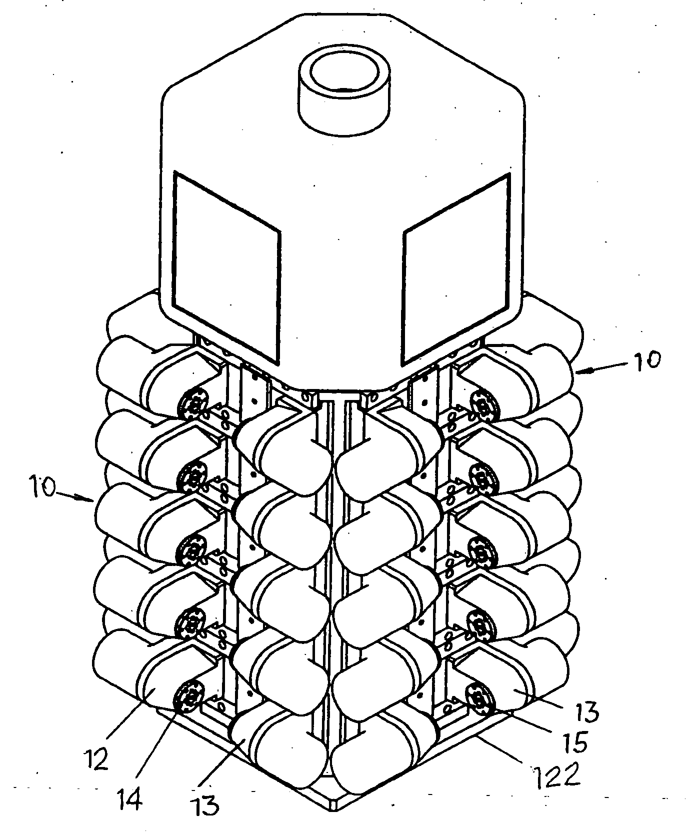
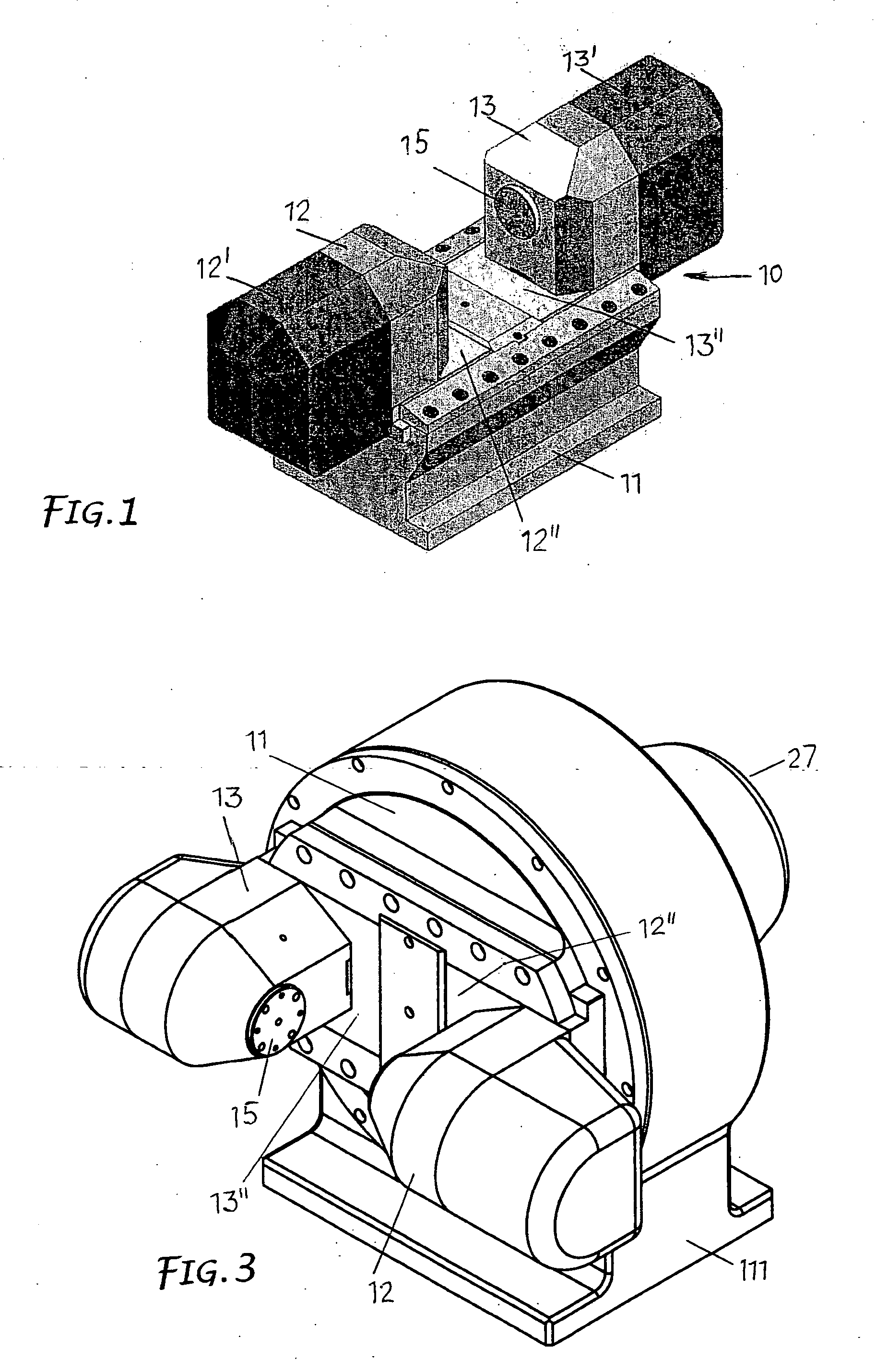
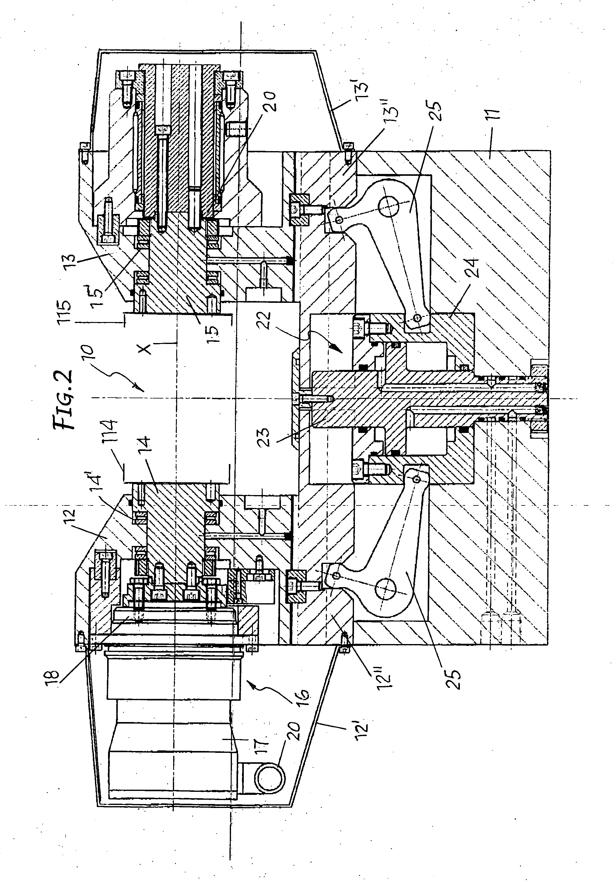
[0024] In the embodiment according to FIGS. 1 and 2, the pieces hold-unit 10 comprises two parallel supports 12, 13 guided on a base body 11 and at least one of them movable in the direction of the other one in order to be able to bring them nearer and move them away as required. A first controlled clamp-holder shaft 14 is rotary mounted on a support 12, while a second clamp-holder shaft 15 is rotary mounted, but in idle state, on the other support 13. The two shafts 14, 15 are on a common axis X, and each one is arranged to be frontally fitted out with a hold-clamp 114, 115 for the piece to be machined. The clamps are usually shaped according to the piece to process and are associated with said shafts in interchangeable way. Both the controlled shaft 14 and the idle shaft 15 are mounted and centred on the respective supports 12, 13 through thrust bearings 14′,15′ or bushings.

[0025] The controlled shaft 14 is moved by a gear-reduction unit 16, for instance by a precision epicycloid...


PUM

PropertyMeasurementUnit
movementsaaaaaaaaaa
shapeaaaaaaaaaa
timeaaaaaaaaaa

Abstract

A pieces hold-unit for machine tools such as workstations, transfer machines and milling machines is provided which comprises two parallel supports (12, 13) placed on a plane with at least a first of said support guided, controlled and movable with respect to the other one in order to approach and move them away, at least a first clamp-holder shaft (14) rotary mounted on the said first support and controlled for rotating, a second clamp-holder shaft (15) mounted on the other of said supports. Each shaft holds a clamp opposite to that of the other shaft, and one gear-reduction unit (16) is located at least on board of the support carrying said first shaft to follow the movements of said support and cause the gradual rotation of said first shaft.

Description

FIELD OF THE INVENTION [0001] The present invention concerns in general the field of machine tools for multiple mechanical machining such as workstations, transfer machines, milling machines and the like, and it refers in particular to pieces hold-units, that is to say vice, to be used in such machines. STATE OF THE TECHNIQUE [0002] Machine tools for automatic multiple machining usually comprise several operating units variously associated with a machine-member which holds the pieces to be processed. [0003] In workstations, for instance, the pieces-holder member can be in the shape of a prismatic body fitted out, on one or more faces, with several clamps designed for receiving and keeping the pieces to be processed. The prismatic body can be provided to rotate on an axis so that the pieces kept by the clamps may be exposed towards the operating units. In such an use the clamps are mostly not revolving, so the effective orientation of the pieces with respect to the tools turns out to...

Claims


Application Information

Patent Timeline
Patent Type & Authority Applications(United States)
IPC IPC(8): B23B31/175B25B1/22B23Q1/48B25B1/18B23Q3/06
CPCB23B31/16216B23Q3/066B25B1/18B25B1/22Y10T29/5129Y10T409/305824Y10T409/30532B23Q1/25B23Q3/06
Inventor FERRARI, ROSARIO
Owner DM2 DI DUNINA GIANFRANCO SRL
Why Eureka
Try Eureka