
Gas diffusion shower head design for large area plasma enhanced chemical vapor deposition

Inactive Publication Date: 2005-10-13
APPLIED MATERIALS INC
View PDF18 Cites 98 Cited by
  • Summary
  • Abstract
  • Description
  • Claims
  • Application Information

AI Technical Summary

Benefits of technology

[0016] In yet another embodiment, a method of cleaning a process chamber comprises placing a substrate in a process chamber, which is coupled to a remote plasma source and the remote plasma source is coupled to a fluorine source, with a diffuser plate having an upstream side and a downstream side, and a plurality of gas passages passing between the upstream and downstream sides, wherein at least one of the gas passages has a first right cylindrical shape for a portion of its length extending from the upstream side, a second coaxial right cylindrical shape with a smaller diameter connected to the first cylindrical shape, a coaxial conical shape connected to the second cylindrical shape for the remaining length of the diffuser plate, with the upstream end of the conical portion having sub

Problems solved by technology

Large gas distribution plates utilized for flat panel processing have a number of fabricating issues that result in high manufacturing costs.
For example, gas flow holes formed through the gas distribution plate are small in diameter relative to thickness of the gas distribution plate, for example a 0.016 inch diameter hole through a 1.2 inch thick plate, resulting in a high frequency of drill bit breakage during hole formation.
Removal of broken drill bits is time consuming and may result in the entire gas distribution plate being scrapped.
Additionally, as the number of gas flow holes formed through the gas distribution plate is proportional to the size of the flat panel, the great number of holes formed in each plate disadvantageously contributes to a high probability of trouble during plate fabrication.
Moreover, the high number of holes coupled with the care required to minimize drill bit breakage results in long fabrication times, thereby elevating fabrication costs.

Method used


Image

  • Gas diffusion shower head design for large area plasma enhanced chemical vapor deposition
  • Gas diffusion shower head design for large area plasma enhanced chemical vapor deposition
  • Gas diffusion shower head design for large area plasma enhanced chemical vapor deposition

Examples


Embodiment Construction

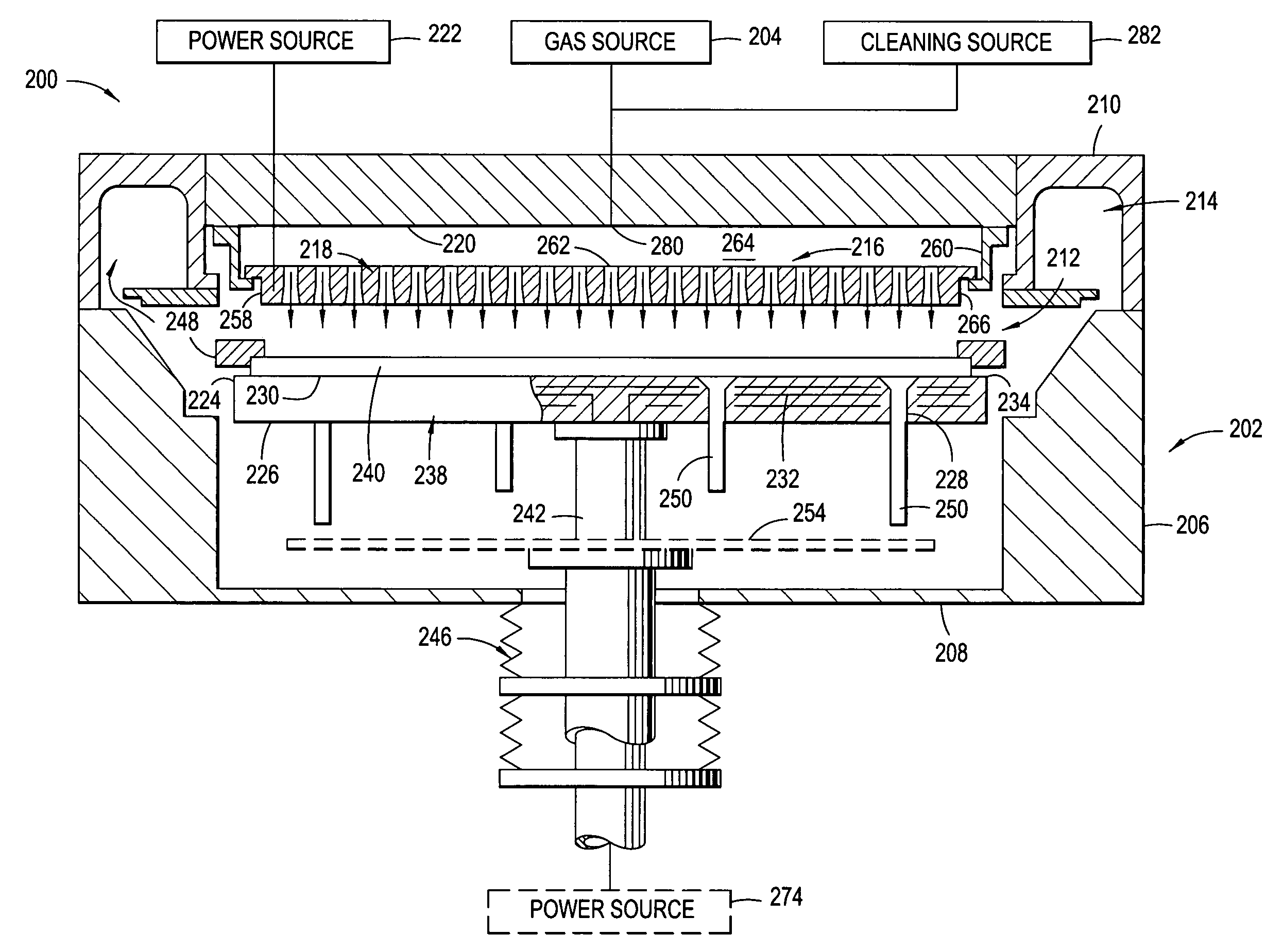
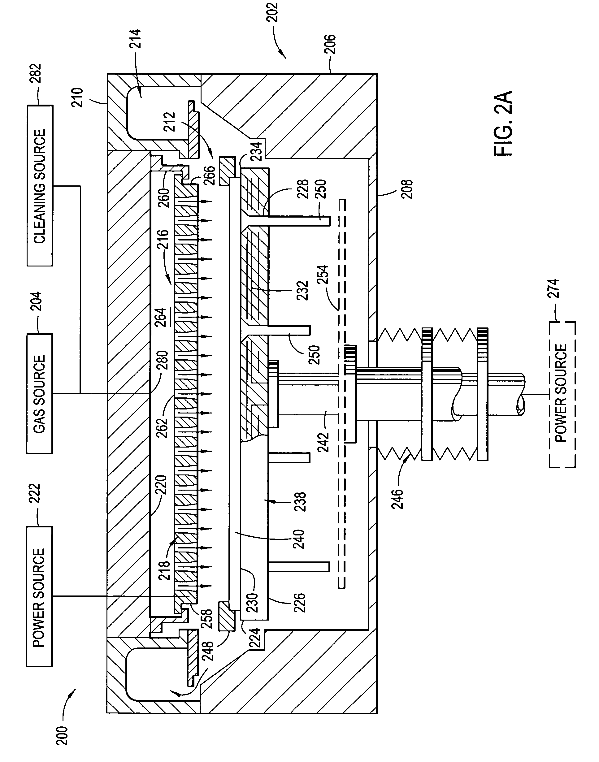
[0031] The invention generally provides a gas distribution plate assembly for providing gas delivery within a processing chamber. The invention is illustratively described below in reference to a plasma enhanced chemical vapor deposition system configured to process large area substrates, such as a plasma enhanced chemical vapor deposition (PECVD) system, available from AKT, a division of Applied Materials, Inc., Santa Clara, Calif. However, it should be understood that the invention has utility in other system configurations such as etch systems, other chemical vapor deposition systems and any other system in which distributing gas within a process chamber is desired, including those systems configured to process round substrates.

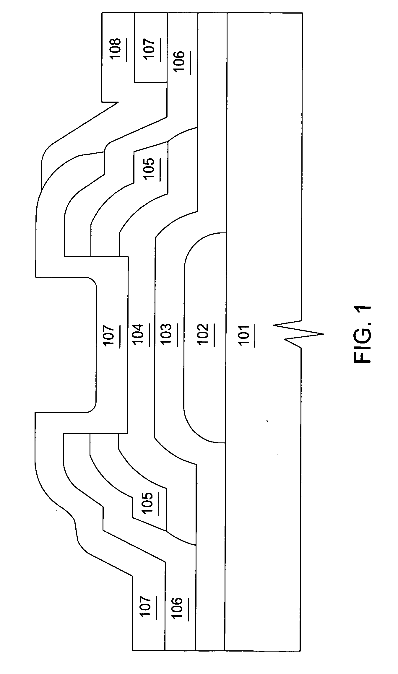
[0032]FIG. 1 illustrates cross-sectional schematic views of a thin film transistor structure. A common TFT structure is the back channel etch (BCE) inverted staggered (or bottom gate) TFT structure shown in FIG. 1. The BCE process is preferred, because th...


PUM

PropertyMeasurementUnit
Lengthaaaaaaaaaa
Thicknessaaaaaaaaaa
Thicknessaaaaaaaaaa

Abstract

Embodiments of a gas distribution plate for distributing gas in a processing chamber are provided. In one embodiment, a gas distribution plate includes a diffuser plate having an upstream side and a downstream side, and a plurality of gas passages passing between the upstream and downstream sides of the diffuser plate. At least one of the gas passages has a right cylindrical shape for a portion of its length extending from the upstream side and a coaxial conical shape for the remainder length of the diffuser plate, the upstream end of the conical portion having substantially the same diameter as the right cylindrical portion and the downstream end of the conical portion having a larger diameter. The gas distribution plate is relatively easy to manufacture and provides good chamber cleaning rate, good thin film deposition uniformity and good thin film deposition rate. The gas distribution plate also has the advantage of reduced chamber cleaning residues on the diffuser surface and reduced incorporation of the cleaning residues in the thin film being deposited.

Description

BACKGROUND OF THE DISCLOSURE [0001] 1. Field of the Invention [0002] Embodiments of the invention generally relate to a gas distribution plate assembly and method for distributing gas in a processing chamber. [0003] 2. Description of the Background Art [0004] Liquid crystal displays or flat panels are commonly used for active matrix displays such as computer and television monitors. Plasma enhanced chemical vapor deposition (PECVD) is generally employed to deposit thin films on a substrate such as a transparent glass substrate (for flat panel) or semiconductor wafer. PECVD is generally accomplished by introducing a precursor gas or gas mixture into a vacuum chamber that contains a flat panel. The precursor gas or gas mixture is typically directed downwardly through a distribution plate situated near the top of the chamber. The precursor gas or gas mixture in the chamber is energized (e.g., excited) into a plasma by applying radio frequency (RF) power to the chamber from one or more ...

Claims


Application Information

Patent Timeline
IPC IPC(8): C23C16/00C23C16/44C23C16/455H01J37/32H01L21/205H01L21/3065H01L21/31H01L21/336H01L29/786
CPCC23C16/4405C23C16/45565H01J37/3244B05B1/005C23C16/45559C23C16/45561H01L21/02274H01L21/02164H01L21/0217H01L21/02126
Inventor CHOI, SOO YOUNGWHITE, JOHN M.GREENE, ROBERT I.
Owner APPLIED MATERIALS INC
Learn More