Replaceable cartridge for liquid hydrogen

a liquid hydrogen and replacement cartridge technology, applied in the field of hydrogen storage, can solve the problem that there is no corresponding system for liquid hydrogen, and achieve the effect of simple and cost-effective replacement cartridges

Inactive Publication Date: 2005-10-13
AIRBUS OPERATIONS GMBH
View PDF57 Cites 21 Cited by
  • Summary
  • Abstract
  • Description
  • Claims
  • Application Information

AI Technical Summary

Benefits of technology

[0015] According to a further embodiment of the present invention, taking into consideration ambient temperatures and requirements, i.e. hydrogen requirements of the consumer, the superinsulation can be designed such that heat transmission from the environment with the ambient temperature to the internal tank by way of the superinsulation is sufficient during operation to cover the consumer's requirement for gaseous hydrogen. It is thus possible in a simple way to provide a replaceable cartridge which “automatically” forms a sufficient quantity of gaseous hydrogen from the liquid hydrogen to cover the requirements of the consumer. This may make it possible to provide a replaceable cartridge which does not require any regulating devices for controlling the quantity of hydrogen delivered. In this way it is possible to provide a simple and cost-effective replaceable cartridge. Moreover, because this embodiment does not involve failure of a regulator system, it is possible to provide a very safe replaceable cartridge.
[0016] According to a further embodiment of the present invention, at least one protective cap is provided for each of the at least one disconnectable connection couplings. For example, this protective cap can protect the connection couplings against mechanical damage. The protective cap can be designed to provide not only mechanical protection, but also a leakage safety device. To this effect, in a space defined by the protective cap, a catalyst can be provided which utilises any hydrogen that evaporates from the connection coupling into said space.
[0017] In an advantageous way this may prevent any accumulation of evaporating hydrogen, for example in any cavities in the surroundings of the replaceable cartridge.
[0018] According to a further embodiment of the present invention, a device for supplying heat to the internal tank is provided. By controlling the heat supplied, an output quantity of gaseous hydrogen can be controlled which can be supplied to the consumer. In an advantageous way it may thus be possible to match the replaceable cartridge to the various fields of application and to the various consumers.

Problems solved by technology

Up to now, no corresponding system has been available for liquid hydrogen.

Method used


Image

  • Replaceable cartridge for liquid hydrogen
  • Replaceable cartridge for liquid hydrogen
  • Replaceable cartridge for liquid hydrogen

Examples


Embodiment Construction

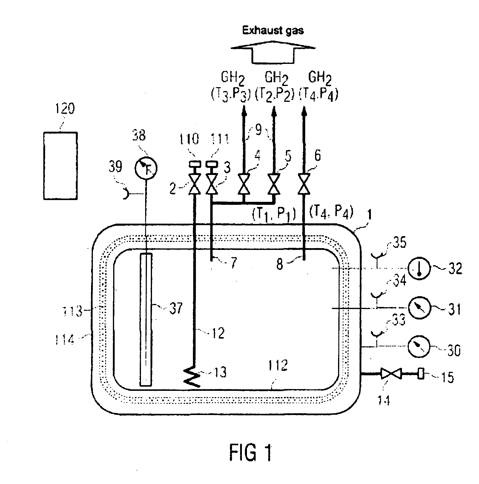
[0030] It should be pointed out that in order to simplify illustration, FIGS. 1 and 4 show automated logic diagrams for various elements. In the following description of FIGS. 1 to 4 identical or corresponding elements have the same reference numbers.

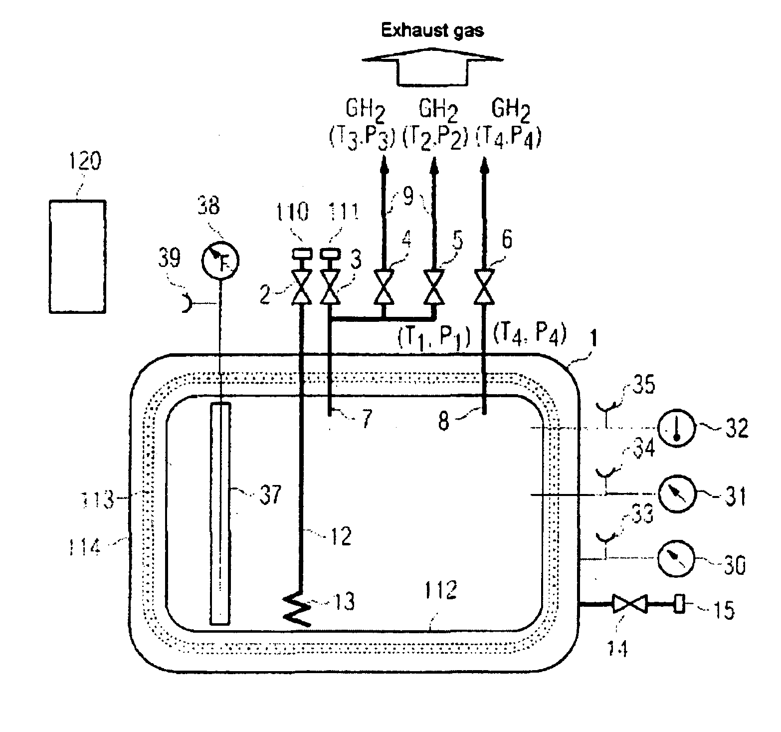
[0031]FIG. 1 shows a section view of a replaceable cartridge comprising an embodiment of the present invention for coupling to a consumer or to a filling station. The replaceable cartridge comprises a plurality of disconnectable connection couplings, which are described in detail below, for connection to the consumer or the filling station, as well as a tank 1 for holding liquid hydrogen. The tank 1 comprises an external tank 114 as well as an internal tank 112. The external tank 114 and the internal tank 112 are thermally decoupled by means of an insulation, for example a superinsulation 113. The superinsulation 113 can for example be implemented by means of a vacuum. Preferably, this decoupling is implemented such that at an ambient ...


PUM

PropertyMeasurementUnit
operating pressureaaaaaaaaaa
temperatureaaaaaaaaaa
energy densityaaaaaaaaaa

Abstract

A replaceable cartridge for coupling to a consumer or to a filling station, wherein the replaceable cartridge comprises at least one disconnectable connection coupling for connection to the consumer or the filling station. Furthermore, the replaceable cartridge comprises a tank for holding liquid hydrogen.

Description

CROSS-REFERENCE TO RELATED APPLICATIONS [0001] This application claims the benefit of the filing date of U.S. Provisional Patent Application No. 60 / 598,257 filed Aug. 3, 2004, the disclosure of which is hereby incorporated herein by reference.BACKGROUND OF THE INVENTION [0002] The present invention relates to the storage of hydrogen, preferably in vehicles, such as for example aircraft. In particular, the present invention relates to a replaceable cartridge for coupling to a consumer or to a filling station, a connection coupling for a consumer or for a filling station, an aircraft comprising a respective replaceable cartridge as well as a method for handling a replaceable cartridge. [0003] In its liquid form, hydrogen has been used for some considerable time in industry and in space technology. In its gaseous form, hydrogen is available in hybrid metal storage devices or pressure tanks. Up to now, no corresponding system has been available for liquid hydrogen. SUMMARY OF THE INVENT...

Claims


Application Information

Patent Timeline
Patent Type & Authority Applications(United States)
IPC IPC(8): B67D99/00F17C1/00
CPCF17C1/00F17C2201/01F17C2201/0104F17C2201/0157F17C2201/035F17C2201/056F17C2203/0391F17C2203/0629F17C2205/0157F17C2205/0332F17C2205/0335F17C2205/037F17C2205/05F17C2221/012F17C2223/0161F17C2223/0192F17C2223/033F17C2223/043F17C2225/0123F17C2225/033F17C2227/0107F17C2227/0306F17C2227/0374F17C2227/0388F17C2250/032F17C2250/0417F17C2250/043F17C2250/0439F17C2250/0491F17C2260/00F17C2265/031F17C2265/032F17C2270/0105F17C2270/0134F17C2270/0168F17C2270/0178F17C2270/0189Y02E60/321Y10T29/4973Y10S220/901Y02E60/32
Inventor WESTENBERGER, ANDREAS
Owner AIRBUS OPERATIONS GMBH
Why Eureka
Try Eureka