Stirred ball mill

Active Publication Date: 2005-10-13
WILLY A BACHOFEN AG
View PDF6 Cites 25 Cited by
  • Summary
  • Abstract
  • Description
  • Claims
  • Application Information

AI Technical Summary

Benefits of technology

[0014] It is the object of the invention to provide a stirred ball mill having a horizontal axis and a novel separation member which does not have the above-mentioned disadvantages an

Problems solved by technology

This may lead to compression of the grinding media before the separation member, which compression is associated with increased wear and increased risk of blockage.
However, the known solutions are very often inadequate for grinding media of D≦0.1 mm.
In further known separation systems, such as, for example, with the use of so-called split-sieve cartridges, the production with small gap widths of ≦0.05 mm proves to be very difficult, which gap widths are moreover scarcely usable in practice.
In addition, the probability that the sieve will be blocked is very high in these cases if grinding media having D≦0.1 mm have to be used, which is necessary in nanotechnology and hence also in the production of nanoparticles.
A further problem arises through the high pressure drop owing to the accumulation of grinding media on the sieve.
A blockage of the outlet, possibly caused by the narrow tolerances at th

Method used


Image

  • Stirred ball mill
  • Stirred ball mill
  • Stirred ball mill

Examples


Embodiment Construction

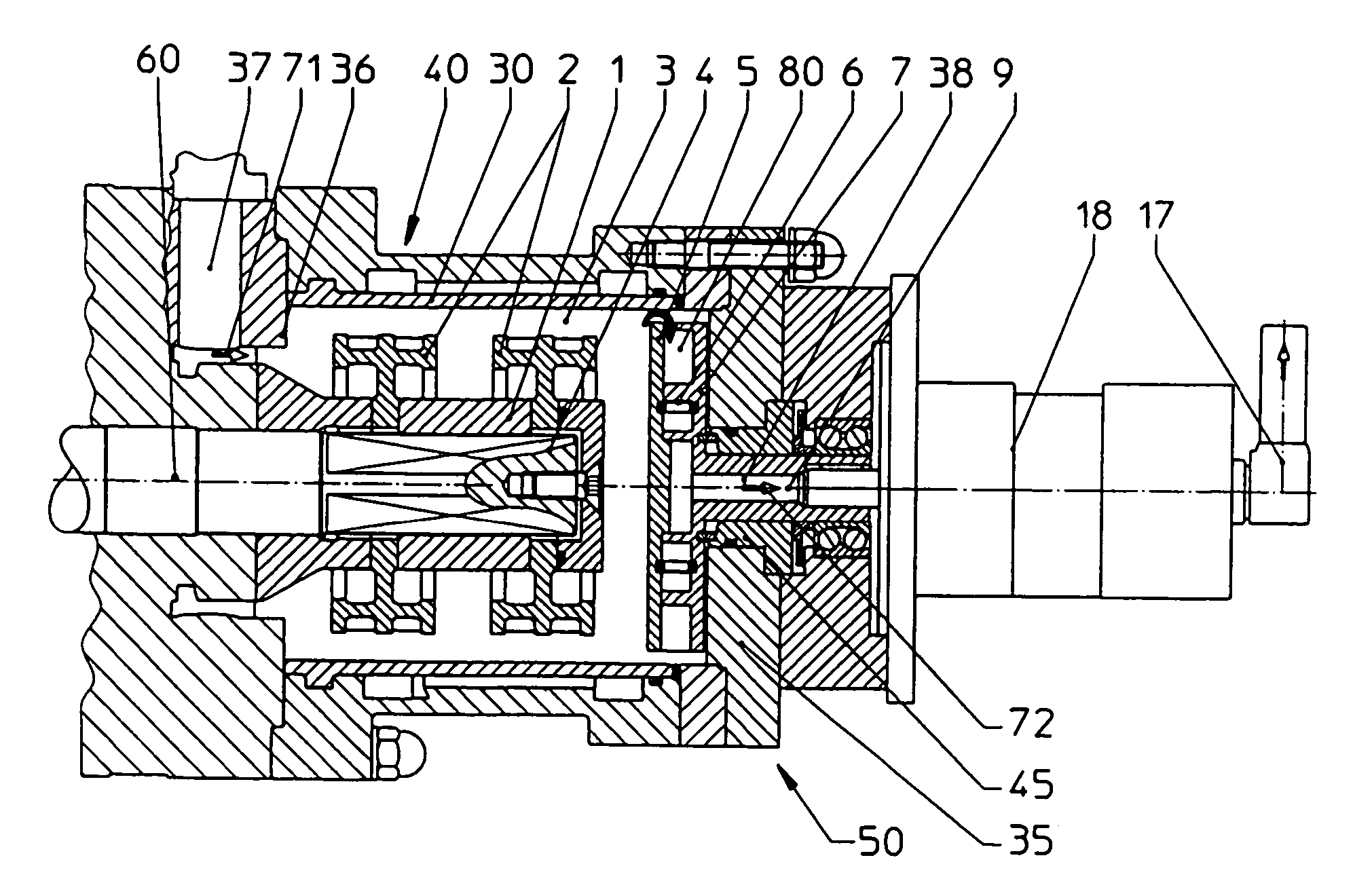
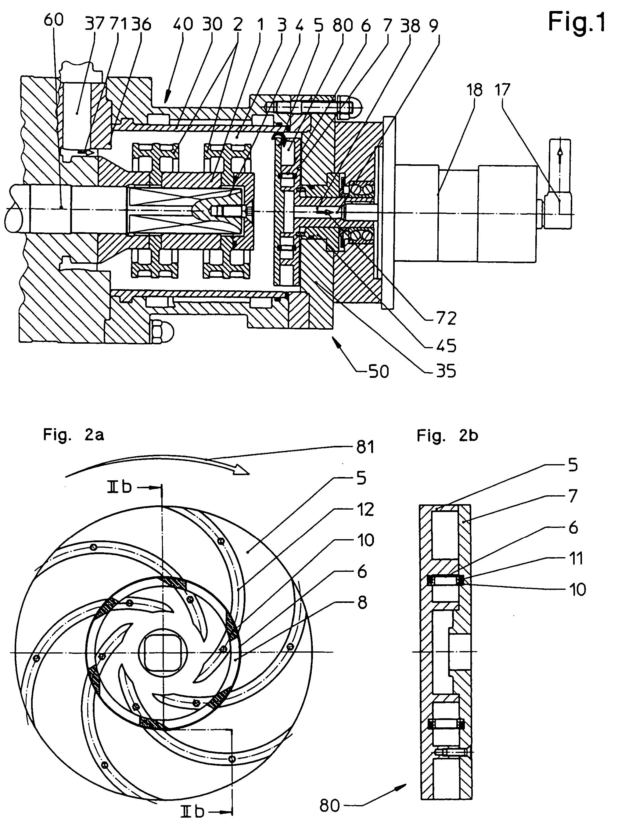
[0023] The grinding chamber of a stirred ball mill is shown only partly in FIG. 1, is denoted as a whole by 50 and has a housing 40 with a horizontal axis 60. The housing 40 has an elongated, substantially cylindrical longitudinal wall 30 and two end walls 35 and 36 which are arranged at both ends of the longitudinal wall 30 and of which the end wall 36 has a material inlet 37 which serves for feeding the material to be milled and the end wall 35 has a material outlet 38 which serves for removing the material.

[0024] A stirrer 1 which has a plurality of paddle wheel-like stirrer members 2, for example two thereof, distributed along the axis 60, is arranged in the interior 3. The shaft 4 of the stirrer 1 is coaxial with the axis 60 and is connected, at its end passing through the end wall 36, to a drive apparatus not shown in the drawing.

[0025] Present in the end wall 35 of the grinding chamber 50 is a separation member 80 which is arranged coaxially with the axis 60 and is connecte...


PUM


Abstract

The horizontally operating stirred ball mill has a cylindrical grinding chamber (50) serving for receiving grinding media, a material inlet (37) arranged at the end of the grinding chamber (50) and opening into the interior (3) of the grinding chamber (50), a material outlet (38) arranged at the other end of the grinding chamber and leading out of the interior (3), a stirrer (1) having a plurality of stirrer members (2) and coaxial with the chamber axis (60), and a separation system present upstream of the material outlet (38) and consisting of a separation member (80) and a drive member which drives said separation member and which separates the grinding media from the ground material and transports them back into the interior (3) of the grinding chamber (50). The separation member (80) has two circular disks (5, 7) which are arranged coaxially with the chamber axis (61) and between which a plurality of conveying or blade elements (12) symmetrically distributed around the midpoint of the disk and leading inwards from the disk edge are arranged, which elements, during operation of the stirred ball mill, generate an opposing pressure on the mixture of material and grinding media, so that, owing to the centrifugal force and the different specific density, the grinding media are separated from the product and are transported back into the interior (3).

Description

BACKGROUND OF THE INVENTION [0001] 1. Field of the Invention [0002] The invention relates to a stirred ball mill having a separation member for separating very small grinding media having a diameter D≦0.1 mm from the product. [0003] Stirred ball mills are used, for example, for comminuting and dispersing solids in a liquid phase or for digesting microorganisms. [0004] 2. Description of the Prior Art [0005] Stirred ball mills known on the market and intended for continuous operation have a cylindrical grinding chamber with a horizontal or vertical axis and have various types of separation members for separating the grinding media from the product in the product outlet region. [0006] The housing of the grinding chamber of a stirred ball mill consists of a longitudinal wall and two end walls arranged at the two ends of the longitudinal wall. It has a material inlet which serves for feeding the material to be ground and a material outlet which serves for removing the material. Moreover,...

Claims


Application Information

Patent Timeline
IPC IPC(8): B02C17/16B02C17/18
CPCB02C17/161B02C17/163
Inventor HEINZELMANN, MARTINSPORNBERGER, STEFAN
Owner WILLY A BACHOFEN AG
Why Eureka
Try Eureka