System and processes for causing the simultaneity of events including controlling a pulse repetition frequency of a pulsed laser for disabling a scanning imaging system

a scanning imaging system and pulsed laser technology, applied in discharge tubes/lamp details, instruments, weapons, etc., can solve the problems of laser-induced damage of array material, inability to disassemble pixel or array, and damage to infrared detector arrays

Active Publication Date: 2005-10-13
TEXTRON INNOVATIONS
View PDF11 Cites 30 Cited by
  • Summary
  • Abstract
  • Description
  • Claims
  • Application Information

AI Technical Summary

Benefits of technology

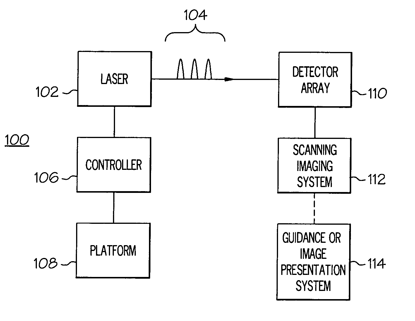
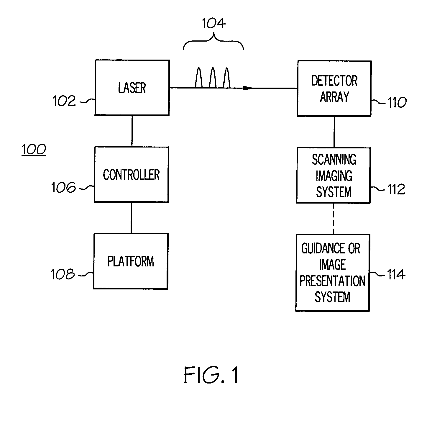
[0012] The present invention is directed to the optimizing of the probability of achieving the simultaneous occurrence of events from different sets of events, one set with a known repetition frequency but unknown phase and the other set with a repetition frequency that is controlled. One or more first sets or families of first events have a first repetition frequency that is predetermined but the phase of which is unknown. An example of such a first family of events could be the scanning rates of one or more scanning imaging systems. A

Problems solved by technology

It has been demonstrated that infrared detector arrays may be damaged and disabled by directing a laser beam at a detector element or pixel in the array.
When focused by imaging optics onto a detector array, a laser beam or pulse, if having sufficient fluence, can cause laser sparks, which in turn can produce laser-induced damage of the array material.
Such resulting laser sparks may remove material by melt, ablation, vaporization and may “drill” down through the infrared detector material to the underlying processing electronics.
Disablement of the pixel or array may occur when a spark induces thermal damage and/or mechanical damage or causes a quantity of charge to move though the layers of the detector into an underlying layer, e.g., readout integrated circuitry (ROIC), multiplexing circuitry, integration circuitry, etc.
Any of such phenomenologies resulting from a laser spark can causes either an open circuit or a short circuit in one of the layers under the detector or array, causing a total shutdown of the functionality of the array.
The focused beam or pulses may further interfere with the normal operation of the array by producing heated plasmas at the detector surfa

Method used


Image

  • System and processes for causing the simultaneity of events including controlling a pulse repetition frequency of a pulsed laser for disabling a scanning imaging system
  • System and processes for causing the simultaneity of events including controlling a pulse repetition frequency of a pulsed laser for disabling a scanning imaging system
  • System and processes for causing the simultaneity of events including controlling a pulse repetition frequency of a pulsed laser for disabling a scanning imaging system

Examples


example 1

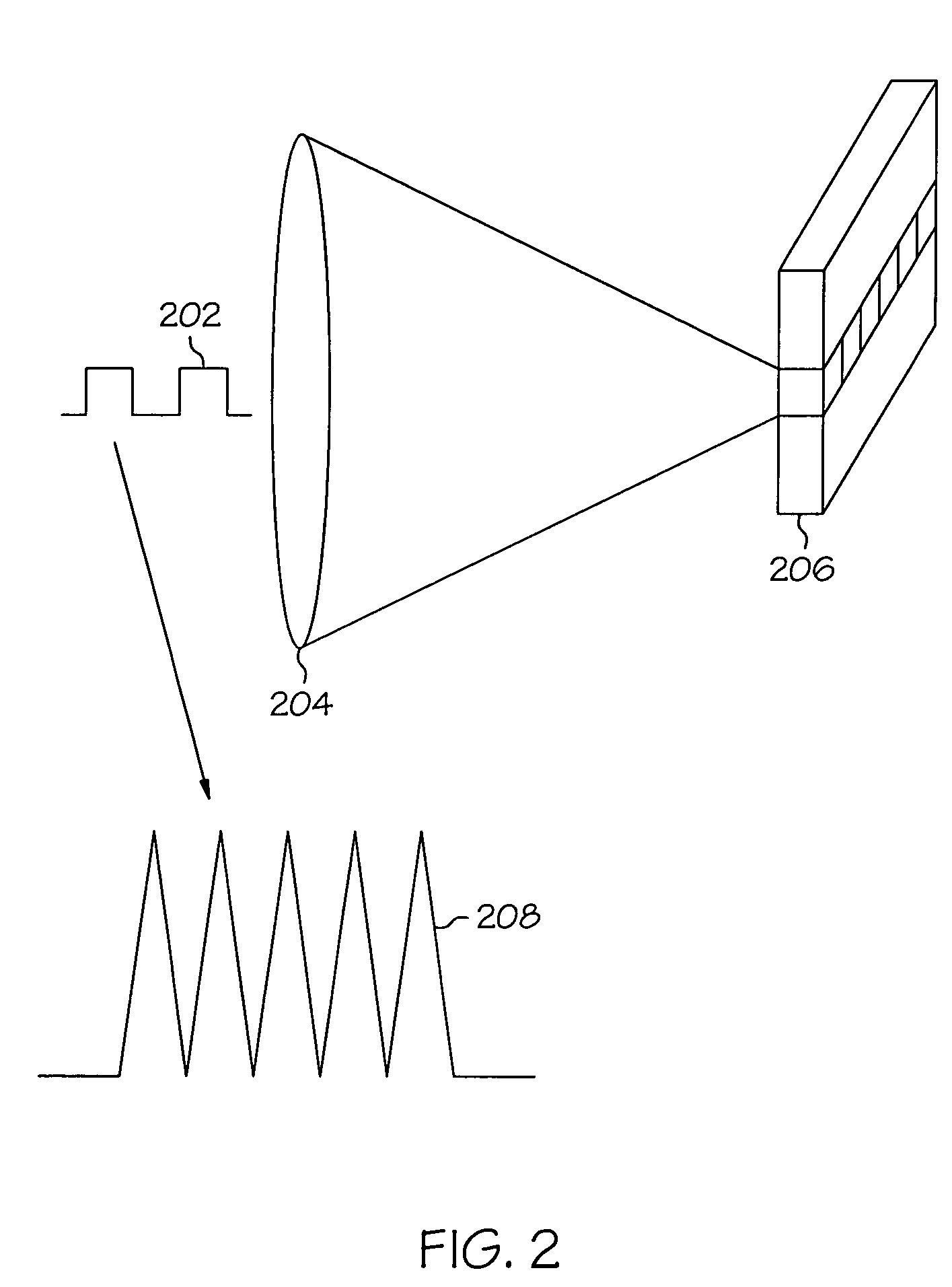
[0057] Controlling a pulsed laser to disable a scanning optical imaging system that has eight lines per frame and a scanning rate of 30 Hz. A scanning optical imaging system can have an internal field of view or image frame that is scanned when a rotating mirror is placed on the optical path within the scanning optical imaging system. The frame can be larger than a detector array placed at the foal plane. For such a system having a frame that is eight times as wide as the detector array, the system has eight lines per frame (LPF) or LPF of eight. As a result, the frame for this system traverses eight detector or line widths as the frame scans past the detector array in the focal plane. Because the rotating mirror has a frequency of repetition, it consequently scans the frame across the detector array at a certain frame rate, e.g., 30 Hz. The frame rate FR when multiplied by the lines per frame determines how many lines in the systems are scanned per second, which is the line rate. F...


PUM


Abstract

A system and processes for causing the simultaneity of events from two or more families of events are described. A repetition rate and modulus of each one the first families of events is determined. A second family of events has a controlled repetition rate that optimizes the simultaneity of a number of events of the second family with a corresponding number of events from the first family within a desired time period. The first families of events can be occurrences of scanning an image of a target across a detector element of a scanning imaging system. The modulus can be a number of lines per frame of the scanning imaging system. Laser pulses having a pulse repetition rate can be events from the second family of events. A system and processes may disable one or more scanning imaging systems by controlling a pulse repetition frequency of a laser output.

Description

BACKGROUND [0001] Optical systems are commonly used in ground-based surveillance systems and in guidance systems of aircraft and missiles to identify and track other objects or aircraft. Such surveillance and guidance or “seeker” systems may be based on infrared detectors (IR), i.e., those that detect light in the infrared region of the spectrum. Such surveillance systems are often referred to as forward looking infrared systems or “FLIRs.” Forward looking infrared imaging systems may be divided into two broad categories, namely, scanning systems and non-scanning or staring systems. For missile guidance there are also non-imaging systems based on a single detector element and modulating the light from a target image. [0002] Staring systems have an image field of view that is fixed in relation to a focal plane of the system. In contrast, scanning imaging systems have an optical element, for example a prism or mirror, that rotates or oscillates, causing an image captured by the system...

Claims


Application Information

Patent Timeline
IPC IPC(8): F41H13/00G01S7/495
CPCF41H13/0056G01S7/495
Inventor VON ROSENBERG, CHARLES WALTER JR.
Owner TEXTRON INNOVATIONS
Why Eureka
Try Eureka