Method for drying sludge by blade drier

A paddle dryer and paddle technology, applied in the direction of dehydration/drying/concentrated sludge treatment, etc., can solve the problems of huge tail gas treatment system, unsatisfactory use effect, difficult long-term operation of equipment, etc., to avoid heat transfer With dry deterioration, good drying effect, small footprint effect

Inactive Publication Date: 2006-10-11
LANZHOU RUIDE DRYING TECH
View PDF1 Cites 16 Cited by
  • Summary
  • Abstract
  • Description
  • Claims
  • Application Information

AI Technical Summary

Problems solved by technology

Due to the high water content of the sludge (generally greater than 50%, up to 90%) and high viscosity, the sludge often sticks to the wall during production with the above dryer, which makes it difficult for the equipment to operate for a long period of time.
Among them, the use of fluidized

Method used


Image

  • Method for drying sludge by blade drier
  • Method for drying sludge by blade drier

Examples


Embodiment 1

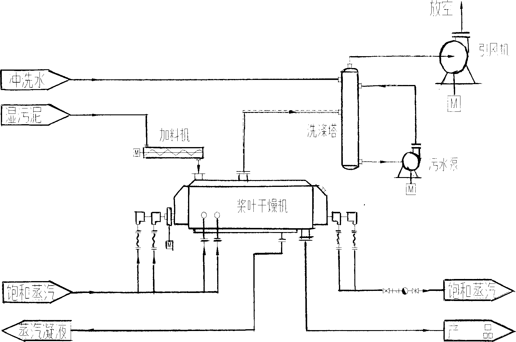
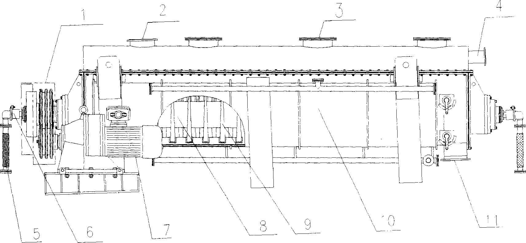
[0022] Such as figure 1 figure 2 As shown, the oily sludge of the oil refinery with a moisture content of 87% is continuously and uniformly added to the paddle dryer (patent number: ZL 01 265998.3) from the feed port 2 of the paddle dryer by a single screw feeder, with 0.6MPa ( G) Saturated steam is the heat medium. The heat medium enters the hollow heat shaft 8 of the paddle dryer and the shell jacket 10 of the paddle dryer through the inlet 5 through the rotary joint 6. There is a wedge-shaped paddle 9 on the heat shaft 8, and the heat shaft 8 is driven by the motor of the transmission system 1 and the reducer 7; the wet material is vaporized under the indirect heating of the heat medium through the heat shaft 8 and the shell jacket 10 of the paddle dryer, and the material is dried while drying on the hollow paddle. Stirring and pushing of the heat shaft 8 moves to the discharge port 11, the product output and humidity are controlled through the rotation speed of the hollo...

Embodiment 2

[0024] The chemical plant biochemical sludge with a moisture content of 82% is continuously and evenly fed into the paddle dryer from the feed port 2 of the paddle dryer through a double-screw conveyor; 0.6MPa (G) saturated steam is used as the heat medium, and the heat medium The inlet 5 enters the hollow blade thermal shaft 8 of the paddle dryer and the shell jacket 10 of the paddle dryer through the rotary joint 6. The thermal shaft 8 is driven by the motor of the transmission system 1 and the reducer 7; the wet material passes through the heat medium Under the indirect heating of the heat shaft 8 and the shell jacket 10 of the paddle dryer, the moisture is vaporized, and while the material is being dried, it moves to the discharge port 11 under the stirring and pushing of the heat shaft 8, and the control of product output and humidity Through the adjustment of the rotating speed of the hot shaft 8 and the height of the overflow plate at the outlet of the dryer, the moistur...


PUM


Abstract

The invention provides a sludge paddle desiccation method, which comprises the following steps: loading wet sludge into a paddle desiccator with a charger, indirectly heating materials through a hollow blade heating shafts and a shell jacket with thermal medium, the heating shafts intermeshied and rotating, with squeezing and relaxation alternative action, materials dried and moving to a discharge door simultaneity. The wet share evaporated in drying process is carried and discharged with carrying gas, and the carrying gas can enter from a carrying gas inlet or the discharge door, and is ejected from exhaust outlet. The heating shafts of the desiccator can be two shafts, or four shafts. The wet share discharged from the desiccator is washed, dedusted and deodorizated with a washing tower to reach the emission standard, and evacuation with a induced fan. The invention has the characters such as small energy consumption, low operating cost, small equipment plot area and equipment investment, big operating flexibility, stable and reliable operation, little entrained dust and material depletion. The invention settles the technical roadblock of huge dedusting equipment, high operating cost of hot-air sludge desiccator or short periodic motion caused by frequently sticking wall in other sludge desiccation. The invention not only make drying in allusion to the characters of high moisture content and high viscosity of sludge, but also is suitable to dry industrial sludge such as oil sludge, catalytic sludge, chemical sludge, biochemistry sludge, and domestic sludge.

Description

technical field [0001] The invention relates to the technical field of sludge drying (drying), and is a paddle dryer for urban domestic sludge and industrial sludge (including various oil sludge, catalytic sludge, chemical sludge, biochemical sludge, etc.) chemical (drying) method. Background technique [0002] The industry generally refers to the drying of municipal domestic sludge and industrial sludge as drying. At present, the drying of sludge at home and abroad mostly uses drum dryers, disc dryers, fluidized bed dryers or other airflow dryers. Due to the high water content of the sludge (generally greater than 50%, up to 90%) and high viscosity, the sludge often sticks to the wall during production with the above-mentioned dryer, which makes it difficult for the equipment to run for a long period. Among them, the use of fluidized bed drying requires a layer of dry material to be laid on the bed before drying, and the use effect is not ideal; hot air drying consumes a ...

Claims


Application Information

Patent Timeline
IPC IPC(8): C02F11/12
Inventor 何德强岳永飞李盈海
Owner LANZHOU RUIDE DRYING TECH
Why Eureka
Try Eureka