Control method of optical fiber amplifier and optical transmission system
Active Publication Date: 2005-10-13
FUJITSU LTD
8 Cites 14 Cited by
AI-Extracted Technical Summary
Problems solved by technology
For the above described optical transmission systems or the like utilizing the optical fiber amplifier, there are common problems, for example, a demand for extending the WDM signal light wavelength band to increase the transmission capacity, or the improvement of an optical signal-to-noise ratio (OSNR) in each repeating interval to realize a superior transmission characteristic.
However, for the forward pumping type Raman amplifier, there have been known a problem of RIN transfer in that a relative intensity noise (RIN) in the pumping light transits into the signal light as the noise, and a problem of PDG (polarization dependent gain) in that a Raman gain significantly depends on a signal light polarization state, (refer to the literature by C. R. S. Fludger et al., “Pump to Signal RIN Transfer in Raman Fiber Amplifier”, Journal of Lightwave Technology Vol. 19, No. 8, 2001, and the literature by J. Zhang et al., “Dependence of Raman Polarization Dependent Gain on Pump Degree of Polarization at High Gain Levels”, OMB4, OM 2001).
However, the conventional technology for extending the signal light band and the conventional technology for improving the OSNR in each repeating interval, cause the following problems.
Therefore, there is caused a problem of high cost in band extension service for when transmission capacity d...
View moreBenefits of technology
[0013] The present invention has been accomplished in view of the above problems relating to optical fiber amplifier control technology, with one object to provide a control method of a rare-earth element doped optical fiber amplifier, and an optical transmission system, for enabling the realization of an ex...
View moreAbstract
In one of control methods of a bidirectional pumping type Raman amplifier according to the present invention, the power of a pumping light supplied to a rare-earth element doped optical fiber is increased or decreased, and a transmission wavelength characteristic of a dynamic gain equalizer is controlled according to a change in a gain wavelength characteristic occurring due to the increase or decrease of the power of the pumping light, to thereby extend a signal light band to either a short wavelength side or a long wavelength side. As a result, it becomes possible to realize a signal light band extension service at a low cost. Moreover, in another control method of the present invention, in a condition where the supply of backward pumping light to the transmission path fiber is shut off, a ratio of a change in the output power of the signal light to a change in the power of the forward pumping light is obtained, and the forward pumping light power is optimized in accordance with this ratio, to obtain a desired level diagram irrespective of a lump loss on the transmission path fiber.
Application Domain
Technology Topic
Image
Examples
- Experimental program(1)
Example
[0040] Embodiments for carrying out a control method of an optical fiber amplifier according to the present invention will be described, with reference to the appended drawings. The same reference numerals denote the same or equivalent parts throughout all drawings.
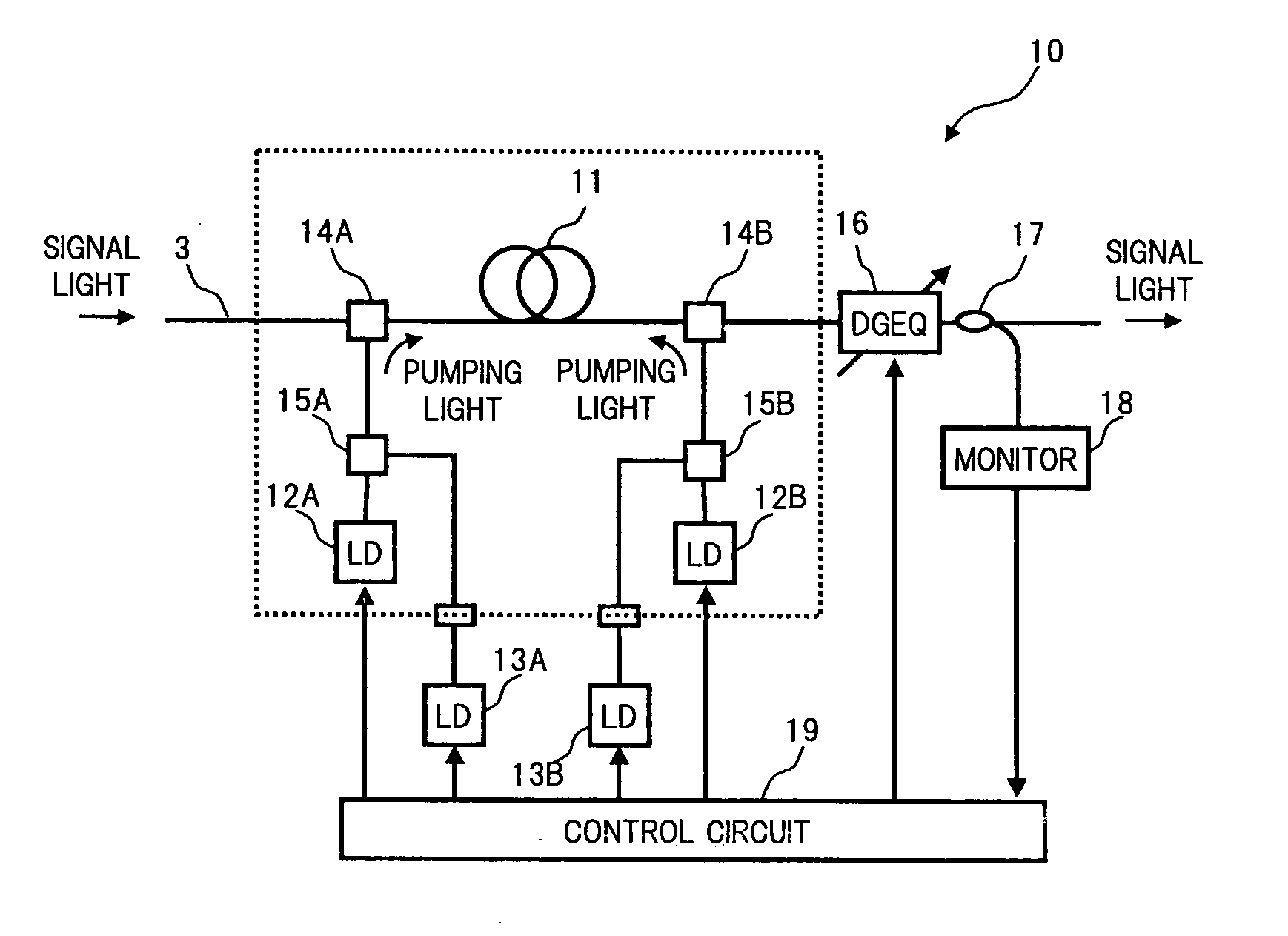
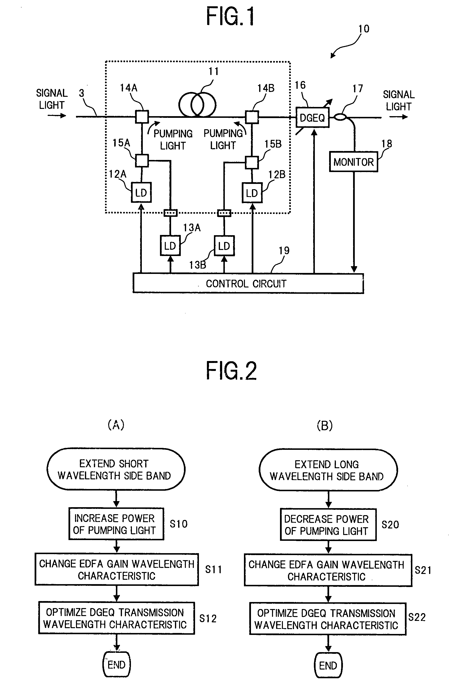
[0041]FIG. 1 is a block diagram showing a configuration of main components of one embodiment of an optical transmission system applied with a control method of an optical fiber amplifier according to a first aspect of the present invention.
[0042] In FIG. 1, the optical transmission system of the present embodiment comprises an optical amplification repeating section 10 including, for example, an amplification fiber 11, pumping light sources 12A and 12B, additional pumping light sources 13A and 13B, multiplexers 14A, 14B, 15A, and 15B, a dynamic gain equalizer (DGEQ) 16, a photocoupler 17, a monitor 18, and a control circuit 19. The overall configuration of the optical transmission system is similar to the conventional configuration shown in (A) of FIG. 15, and the optical amplification repeating section 10 corresponds to each repeater 4 on a transmission path fiber 3. Moreover, a portion enclosed by the dotted line in the figure is similar to the configuration of the conventional rare-earth element doped optical fiber amplifier.
[0043] More specifically, for the amplification fiber 11 constituting the optical amplification repeating section 10, a well-known rare-earth element doped optical fiber having a core doped with a rare-earth element such as erbium or the like, is used.
[0044] Each of the pumping light sources 12A and 12B generates a pumping light of a required wavelength band capable to pump the rare-earth element in the amplification fiber 11. For example, in the case where an erbium doped optical fiber (EDF) is used as the amplification fiber 11, the wavelength bands of the pumping light sources 12A and 12B are set to 980 nm band, 1480 nm band or the like.
[0045] The additional pumping light sources 13A and 13B are, as described below, pumping light sources added in order to extend a signal light amplification band in the amplification fiber 11 to a short wavelength side, thereby extending a signal light band. The additional pumping light source 13A generates a pumping light having a wavelength slightly different to that of the pumping light source 12A, or a pumping light having the same wavelength as that of the pumping light source 12A with a polarization state different from that of the pumping light source 12A. The additional pumping light source 13B generates a pumping light having a wavelength slightly different to that of the pumping light source 12B, or a pumping light having the same wavelength as that of the pumping light source 12B with a polarization state different from that of the pumping light source 12B.
[0046] The multiplexer 14A supplies the pumping light output from the pumping light source 12A to the amplification fiber 11 from a forward direction (signal light input side). The multiplexer 14B supplies the pumping light output from the pumping light source 12B to the amplification fiber 11 from a backward direction (signal light output side). A typical WDM signal light coupler or the like can be used as the multiplexers 14A and 14B. Note, a configuration of bidirectional pumping type is described here. However the present invention is not limited to this, and can be applied to a rare-earth element doped optical fiber amplifiers of forward pumping type configuration or a backward pumping type configuration.
[0047] The multiplexer 15A multiplexes the pumping light output from the pumping light source 12A and the pumping light output from the additional pumping light source 13A, to give the multiplexed light to the multiplexer 14A. The multiplexer 15B multiplexes the pumping light output from the pumping light source 12B, and the pumping light output from the additional pumping light source 13B, to give the multiplexed light to the multiplexer 14B. In the case where the wavelength of each of the pumping light sources 12A and 12B is slightly different from the wavelength of each of the additional pumping light sources 13A and 13B, the WDM coupler can be used for each of the multiplexers 15A and 15B. On the other hand, in the case where the wavelength of each of the pumping light sources 12A and 12B is the same as the wavelength of each of the additional pumping light sources 13A and 13B, but the polarization states are different from each other, a polarization combiner can be used.
[0048] The dynamic gain equalizer 16 is a well-known optical device, which receives a WDM signal light having been propagated through the amplification fiber 11 supplied with the pumping lights, to be amplified, and can transmit the input light in accordance with a transmission wavelength characteristic controlled according to a control signal from the control circuit 19.
[0049] The photocoupler 17 branches a part of the WDM signal light transmitted through the dynamic gain equalizer 16, to send the branched light to the monitor 18. The monitor 18 measures a spectrum of the branched light from the photocoupler 17 by a typical method, and based on the measurement result, monitors a wavelength characteristic of the power of the WDM signal light output from the optical amplification repeating section 10.
[0050] The control circuit 19 controls the power of each of the pumping lights supplied to the amplification fiber, and the transmission characteristic of the dynamic gain equalizer 16 by mutually associating them, according to the wavelength band setting for the WDM signal light input to the optical amplification repeating section 10 and the monitor result in the monitor 18.
[0051] An operation of the optical transmission system having the above configuration will be described.
[0052] In the present optical transmission system, the WDM signal light transmitted from a transmission terminal 1 (FIG. 15) to the transmission path fiber 3 is repeatedly transmitted to a reception terminal 2 while being amplified by the optical amplification repeating sections 10 disposed in plural numbers on the transmission path fiber 3. In each of the optical amplification repeating sections 10, the WDM signal light propagated through the transmission path fiber 3 is sent to the amplification fiber 11 via the multiplexer 14A. The pumping light from the pumping light source 12A and the pumping light from the additional pumping light source 13A are multiplexed by the multiplexer 15A to be supplied to the amplification fiber 11 as a forward pumping light via the multiplexer 14A, and also, the pumping light from the pumping light source 12B and the pumping light from the additional pumping light source 13B are multiplexed by the multiplexer 15B to be supplied to the amplification fiber 11 as a backward pumping light via the multiplexer 14B, so that the rare-earth element (erbium in this case) in the amplification fiber 11 is pumped by these pumping lights.
[0053] The power of each of the pumping lights supplied from both directions to the amplification fiber 11 at this time is controlled to a level according to a wavelength band of the WDM signal light, as a result that a pumping state of each of the pumping light sources 12A and 12B or each of the additional pumping light sources 13A and 13B, is adjusted in accordance with the control signal output from the control circuit 19, as described below. Details of the control of the power of the pumping light by the control circuit 19 will be described later.
[0054] The WDM signal light being propagated through the amplification fiber 11 supplied with the pumping lights is amplified due to a stimulated emission effect of the erbium, and the amplified WDM signal light is given to the dynamic gain equalizer 16 via the multiplexer 14B. In the dynamic gain equalizer 16, the gain equalization on the WDM signal light is performed in accordance with the transmission characteristic controlled by the control signal from the control circuit 19. Note, gain equalization means that the optical power corresponding to each wavelength of the WDM signal light adjusted to match or approach a required level. Then, the WDM signal light transmitted through the dynamic gain equalizer 16 is sent to the transmission path fiber 3 in the next repeating interval, and a part thereof is branched by the photocoupler 17 and given to the monitor 18, in which the wavelength characteristic of the output light power is monitored.
[0055] Here, the control of the additional pumping light sources 13A and 13B and the dynamic gain equalizer 16 by the control circuit 19 will be described in detail, referring to the flowchart in FIG. 2.
[0056] For example, assuming the case where transmission capacity demands are increased after the installation of the present optical transmission system, and it is required to extend the signal light wavelength band to the short wavelength side or a long wavelength side, then the control circuit 19 controls the power of each of the pumping lights supplied to the amplification fiber 11, and the transmission characteristic of the dynamic gain equalizer 16 by mutually associating them, in accordance with the algorithm for band extension to the short wavelength side as exemplified in (A) of FIG. 2, or in accordance with the algorithm for band expansion to the long wavelength side as exemplified in (B) of FIG. 2.
[0057] More specifically, in the case where the wavelength band of the signal light is extended to the short wavelength side, at first in step 10 in (A) of FIG. 2 (indicated by S10 in the flowchart, with similar notations hereunder), the control signal for increasing the pumping light power supplied to the amplification fiber 11 is generated by the control circuit 19, to be output to each of the additional pumping light sources 13A and 13B.
[0058] In step 11, drive states of the additional pumping light sources 13A and 13B are controlled in accordance with the control signals from the control circuit 19, and the power of each of the pumping lights output from the additional pumping light sources 13A and 13B is adjusted to reach a required level. As a result, as shown in a band extension example centered on a C-band in FIG. 3 and a band extension example centered on an L-band in FIG. 4, a gain wavelength characteristic of optical amplification generated in the amplification fiber 11 using the EDF has a characteristic in which the wavelength band generating an effective gain extends to the short wavelength side (thin line), compared to a characteristic prior to band extension (thick line) in which the pumping light power is set to be in a condition similar to the conventional condition. Furthermore, the whole level of the gain wavelength characteristic rises with the increase of the pumping light power, and also, a change occurs in a shape of the gain wavelength characteristic. The increase of gain and the change in the wavelength shape due to the increase of the pumping light power are absorbed, by optimizing the transmission wavelength characteristic of the dynamic gain equalizer 16 in the next step 12.
[0059] More specifically, in step 12, the control signal for optimizing the transmission wavelength characteristic of the dynamic gain equalizer 16 corresponding to the increase of the pumping light power, is generated by the control circuit 19, to be output to the dynamic gain equalizer 16. In the dynamic gain equalizer 16, the transmission wavelength characteristic is dynamically controlled in accordance with the control signal from the control circuit 19, and the gain equalization and level adjustment of the WDM signal light output from the amplification fiber 11 is performed. Moreover, here, the wavelength characteristic of the WDM signal light gain equalized in the dynamic gain equalizer 16 is monitored by the photocoupler 17 and the monitor 18, and the monitor result is fed back to the control circuit 19, to be reflected in the optimization control of the dynamic gain equalizer 16.
[0060] On the other hand, in the case where the wavelength band of the signal light is extended to the long wavelength side, in step 20 in (B) of FIG. 2, the control signal for decreasing the pumping light power to be supplied to the amplification fiber 11 is generated by the control circuit 19, to be output to each of the pumping light sources 12A and 12B.
[0061] In step 21, drive states of the pumping light sources 12A and 12B are controlled in accordance with the control signals from the control circuit 19, and the power of each of the pumping lights output from the pumping light sources 12A and 12B is adjusted to reach a required level. As a result, as shown in the band extension examples in FIG. 3 and FIG. 4, the gain wavelength characteristic of optical amplification generated in the amplification fiber 11 has a characteristic in which the wavelength band generating an effective gain extends to the long wavelength side (dotted line), compared to a characteristic prior to band extension (bold line) in which the pumping light power is set to be in a condition similar to the conventional condition. Furthermore, the whole level of the gain wavelength characteristic is lowered with the decrease of pumping light power, and also, a change occurs in the shape of the gain wavelength characteristic.
[0062] In the next step 22, the control signal for optimizing the transmission wavelength characteristic of the dynamic gain equalizer 16 corresponding to the decrease of the pumping light power, is generated by the control circuit 19, and, as in step 12, a feedback control of the dynamic gain equalizer 16 is executed in accordance with the control signal from the control circuit 19.
[0063] In the above manner, according to the optical transmission system of the present embodiment, the pumping light power to be supplied to the amplification fiber 11 is increased or decreased, and also the transmission wavelength characteristic of the dynamic gain equalizer 16 is optimized corresponding to the change in the gain wavelength characteristic occurring due to the increase or decrease in the pumping light power, so that the amplification band of the rare-earth element doped optical fiber amplifier can be readily extended to the short wavelength side or the long wavelength side. As a result, differently from the conventional example shown in (B) of FIG. 15, the signal light band can be extended without adding an optical fiber amplifier of different band. Therefore, a band extension service can be provided at a minimum cost when transmission capacity demands are increased after the installation of the system and so on. Moreover, since the extension of the signal light band in the present embodiment can be performed during the existing wavelength operation (in-service), the convenience in terms of system operation is excellent.
[0064] In the above embodiment, one example has been shown where the dynamic gain equalizer 16 is arranged on the latter stage of the rare-earth element doped optical fiber amplifier. However, a positional relationship of the rare-earth element doped optical fiber amplifier and dynamic gain equalizer in the present invention is not limited to the above example. For example, the present invention is applicable to an arbitrary configuration assumable to be used as the optical amplification repeating section, such as a configuration in which a dynamic gain equalizer is arranged between stages of a two-staged rare-earth element doped optical fiber amplifier.
[0065] Further, the erbium doped optical fiber amplifier has been proposed as one example of the rare-earth element doped optical fiber amplifier. However, also for an optical fiber amplifier doped with rare-earth element other than erbium, it is possible to realize the extension of the signal light band, by increasing or decreasing the pumping light power and the optimization of the dynamic gain equalizer.
[0066] Moreover, the wavelength characteristic of the WDM signal light output from the dynamic gain equalizer has been monitored, to feedback control the dynamic gain equalizer. However, the constitution may be such that optimum conditions of the dynamic gain equalizer corresponding to the setting of the pumping light power are previously specified, to be stored in a memory or the like, and then when the extension of the signal light band becomes necessary, the stored data is referred to, to determine an appropriate condition. In this manner, the output monitor can be omitted, and hence a system of lower cost may be provided.
[0067] Next is a description of another embodiment of an optical transmission system applied with the control method of the optical fiber amplifier according to the first aspect of the present invention.
[0068]FIG. 5 is a block diagram showing a configuration of main components of an optical transmission system of the above another embodiment.
[0069] In FIG. 5, the optical transmission system of this embodiment is configured so that, in the above optical transmission system shown in FIG. 1, a distributed Raman amplifier 20 using the transmission path fiber 3 as the amplification medium, is incorporated in each of the optical amplification repeating sections 10 to improve a noise characteristic in each repeating interval. The Raman amplifier 20 comprises, for example, a Raman amplification pumping light source 21, an additional Raman amplification pumping light source 22, and multiplexers 23 and 24.
[0070] More specifically, the Raman amplification pumping light source 21 generates a pumping light having the required wavelength and power, which are capable to cause the Raman amplification on the WDM signal light being propagated through the transmission path fiber 3. In the Raman amplification, in the case where a silica-type optical fiber, for example, is used as the transmission path fiber 3 (the amplification medium), a gain peak occurs at a frequency lower by 13.2 THz than a frequency of the pumping light. Therefore, a wavelength of the Raman amplification pumping light source 21 is set in a band on the short wavelength side by an approximately 100 nm to the C-band signal light, for example. The output light power of the Raman amplification pumping light source 21 is controlled to a required level in accordance with the control signal from the control circuit 19.
[0071] The additional Raman amplification pumping light source 22 is a pumping light source, which is added to extend a Raman amplification band corresponding to the extension of the amplification band in the latter staged rare-earth element doped optical fiber amplifier. A wavelength of the additional Raman amplification pumping light source 22 is set according to the signal light band to be extended, and is set to a value fundamentally different from the wavelength of the Raman amplification pumping light source 21. The output light power of the additional Raman amplification pumping light source 22 is also controlled to a required level in accordance with the control signal from the control circuit 19.
[0072] The multiplexer 23 supplies the pumping light output from the Raman amplification pumping light source 21 to the transmission path fiber 3 from the backward (signal light output side). Further, the multiplexer 24 multiplexes the pumping light output from the Raman amplification pumping light source 21 and a pumping light output from the additional Raman amplification pumping light source 22, to give the multiplexed light to the multiplexer 23. As a specific example of the multiplexers 23 and 24, the typical WDM coupler or the like can be used.
[0073] In the optical transmission system having the above configuration, the WDM signal light generated in the transmission terminal 1 (see FIG. 15) is transmitted to the transmission path fiber 3. The respective pumping lights from the Raman amplification pumping light source 21 and the additional Raman amplification pumping light source 22 whose drive states are controlled by the control circuit 19, are supplied to the transmission path fiber 3 via the multiplexers 23 and 24, and the Raman amplification pumping lights are propagated through the transmission path fiber 3 in a direction opposite to the propagation direction of the signal light. As a result, the WDM signal light being propagated through the transmission path fiber 3 is amplified by Raman effect to reach the optical amplification repeating section 10.
[0074] The WDM signal light amplified by Raman effect in the transmission path fiber 3 is sent to the amplification fiber 11 via the multiplexer 14A in the same manner as in the above embodiment shown in the FIG. 1, to be amplified due to the stimulated emission effect of the erbium or the like which is pumped upon receipt of the supply of the pumping lights from the pumping light sources 12A and 12B and the additional pumping light sources 13A and 13B, whose drive states are controlled by the control circuit 19. The WDM signal light propagated through the amplification fiber 11 to be amplified is given to the dynamic gain equalizer 16 whose transmission wavelength characteristic is controlled in accordance with the control signal light from the control circuit 19, to be gain equalized. Then, the WDM signal light transmitted through the dynamic gain equalizer 16 is sent to the transmission path fiber 3 in the next repeating interval, and a part thereof is branched by the photocoupler 17 and given to the monitor 18, in which the wavelength characteristic of the output light power is monitored.
[0075] Here, the control operation of the control circuit 19 in this embodiment will be described in detail, with reference to a flowchart of FIG. 6.
[0076] In the same manner as the above description of operation in reference to FIG. 2, for example, assuming the case where transmission capacity demands are increased after the installation of the present optical transmission system, and it is required to extend the signal light wavelength band to the short wavelength side or the long wavelength side, then the control circuit 19 controls the pumping light power supplied to the transmission path fiber 3, the pumping light power supplied to the amplification fiber 11 and the transmission characteristic of the dynamic gain equalizer 16 by mutually associating them, in accordance with the algorithm for band extension to the short wavelength side as exemplified in (A) of FIG. 6, or in accordance with the algorithm for band expansion to the long wavelength side as exemplified in (B) of FIG. 6.
[0077] More specifically, in the case where the wavelength band of the signal light is extended to the short wavelength side, at first in step 30 in (A) of FIG. 6, the control signal for increasing the pumping light power supplied to the amplification fiber 11 is generated by the control circuit 19, to be output to each of the additional pumping light sources 13A and 13B. Then, in step 31, the drive states of the additional pumping light sources 13A and 13B are controlled in accordance with the control signals from the control circuit 19, and the power of each of the pumping lights output from the additional pumping light sources 13A and 13B is adjusted to reach a required level. As a result, the gain wavelength characteristic of the optical amplification in the amplification fiber 11 is extended to the short wavelength side, and also the whole level of the gain rises, so that a change also occurs in the wavelength shape.
[0078] Next, in step 32, the wavelength or power of the Raman amplification pumping light supplied to the transmission path fiber 3 is adjusted so that the Raman amplification wavelength band in the transmission path fiber 3 is also extended to the short wavelength side corresponding to the extension of the signal light band to the short wavelength side. Here, for example, the Raman amplification pumping light source 22 having the wavelength shorter than the wavelength of the Raman amplification pumping light source 21 is added, so that the Raman amplification wavelength band is extended to the short wavelength side. The power of the light output from each of the Raman amplification pumping light source 21 and the additional Raman amplification pumping light source 22 is set to an optimum level by being mutually associated with the control of the transmission wavelength characteristic of the dynamic gain equalizer 16 performed in the next step 33, so that the desired gain equalization on the WDM signal light is realized, and also the OSNR of optical signals of respective wavelengths contained in the WDM signal light is most flat. In the optimization of the Raman amplification pumping light power and the transmission wavelength characteristic of the dynamic gain equalizer 16, more specifically, it is preferable to optimize the transmission wavelength characteristic of the dynamic gain equalizer 16, so that a slope is provided so that the power of the Raman amplification pumping light on the short wavelength side is relatively greater than that on the long wavelength side, and the wavelength deviation of a Raman gain occurring according to the slope is flattened by the dynamic gain equalizer 16.
[0079] Here, the Raman amplification pumping light source is added to cope with the extension to the short wavelength side of the signal light band. However, for example, in the case where a plurality of pumping light sources having different wavelengths is utilized as the Raman amplification pumping light source 21, it is also possible to extend the Raman amplification wavelength band to the short wavelength side by increasing the output power of the pumping light sources on the short wavelength side among the plurality of pumping light sources.
[0080] On the other hand, in the case where the wavelength band of the signal light is extended to the long wavelength side, in step 40 in (B) of FIG. 6, the control signal for decreasing the pumping light power to be supplied to the amplification fiber 11 is generated by the control circuit 19, to be output to each of the pumping light sources 12A and 12B. Then, in step 41, the drive states of the pumping light sources 12A and 12B are controlled in accordance with the control signals from the control circuit 19, and the power of each of the pumping lights output from the pumping light sources 12A and 12B is adjusted to reach a required level. As a result, the gain wavelength characteristic of the optical amplification in the amplification fiber 11 is extended to the long wavelength side, and also the whole level of the gain is lowered, so that a change also occurs in the wavelength shape.
[0081] Next, in step 42, the wavelength or power of the Raman amplification pumping light supplied to the transmission path fiber 3 is adjusted so that the Raman amplification wavelength band in the transmission path fiber 3 is also extended to the long wavelength side corresponding to the extension of the signal light band to the long wavelength side. Here, for example, the Raman amplification pumping light source 22 having the wavelength longer than the wavelength of the Raman amplification pumping light source 21 is added, so that the Raman amplification wavelength band is extended to the long wavelength side. The power of the light output from each of the Raman amplification pumping light source 21 and the additional Raman amplification pumping light source 22 is set to an optimum level by being mutually associated with the control of the transmission wavelength characteristic of the dynamic gain equalizer 16 performed in the next step 43, so that the desired gain equalization on the WDM signal light is realized, and also the OSNR of optical signals of respective wavelengths contained in the WDM signal light is most flat. A preferable specific example of the optimization of the Raman amplification pumping light power and the transmission wavelength characteristic of the dynamic gain equalizer 16 is similar to that for extending to the short wavelength side.
[0082] In the above manner, according to the optical transmission system of the present embodiment, the same effect can be obtained as with the above embodiment shown in the FIG. 1, and also the Raman amplifier 20 using the transmission path fiber 3 as the amplification medium is incorporated to control simultaneously the Raman amplification pumping light corresponding to the extension of the signal light band, so that the level of the WDM signal light input to the amplification fiber 11 of each optical amplification repeating section 10 rises due to the Raman amplification. Therefore, it becomes possible to improve the OSNR in each repeating interval. Moreover, by increasing or decreasing the power of the pumping light supplied to the amplification fiber 11 in order to extend the signal light band, the gain of the rare-earth element doped optical fiber amplifier is increased or decreased. However, even in the case where the increase or decrease of the gain exceeds the range where the increase or decrease of the gain can be absorbed by the dynamic gain equalizer 16, by controlling the transmission wavelength characteristic of the dynamic gain equalizer 16 in cooperation with the control of the Raman gain in the transmission path fiber 3, the level diagram of entire optical amplifier repeating node including the Raman amplifier 20, can be reset. Therefore, the signal light band can be extended across a wider range.
[0083] Next, an optical transmission system applied with a control method of an optical fiber amplifier according to a second aspect of the present invention.
[0084]FIG. 7 is a block diagram showing a configuration of main components of one embodiment of the optical transmission system applied with the control method of an optical fiber amplifier according to the second aspect of the present invention. Further, FIG. 8 is a diagram showing the overall configuration of the optical transmission system.
[0085] In the optical transmission system of the present embodiment, for example as shown in FIG. 8, a plurality of repeaters 4 are arranged on the transmission path fiber 3 connecting between the transmission terminal (rx) 1 and the reception terminal (Rx) 2, and also a bidirectional pumping type Raman amplifying section 30, which uses the transmission path fiber 3 between each repeater 4 as the amplification medium to supply pumping lights from both directions, and amplifies the WDM signal light being propagated through the transmission path fiber 3 by Raman effect, is arranged for each repeating interval. The bidirectional pumping type Raman amplifying section 30 in each repeating interval, for example as shown in FIG. 7, includes Raman amplification pumping light sources (LD) 31A and 31B, multiplexers 32A and 32B, a photocoupler 33, a monitor 34, an operation circuit 35, and a control circuit 36. As each repeater 4, there may be used a typical repeater applied to a well-known optical transmission system, or an optical amplification repeating section applied with the first aspect of the present invention as shown in FIG. 1 or FIG. 5.
[0086] More specifically, each of the Raman amplification pumping light sources 31 A and 31 B generates a pumping light having the required wavelength and power, which are capable to cause the Raman amplification on the WDM signal light being propagated through the transmission path fiber 3. Here, the pumping light output from each of the Raman amplification pumping light sources 31A and 31B is constituted by a single wavelength.
[0087] The multiplexer 32A supplies the pumping light output from the Raman amplification pumping light source 31A to the transmission path fiber 3 from a forward direction (signal light input side). The multiplexer 32B supplies the pumping light output from the Raman amplification pumping light source 31 B to the transmission path fiber 3 from a backward direction (signal light output side). As a specific example of the multiplexers 32A and 32B, the typical WDM coupler or the like can be used.
[0088] The photocoupler 33 branches a part of the WDM signal light which is propagated through the transmission path fiber 3 to be input to the repeater 4, and sends the branched light to the monitor 34. The monitor 34 measures the power of the branched light from the photocoupler 33, and monitors the output power of the WDM signal light propagated through the transmission path fiber 3 to be amplified by Raman effect.
[0089] The operation circuit 35 calculates a set value of the pumping light power in consideration of an influence by a lump loss existing on the transmission path fiber 3, as described below, based on the monitored value of the signal light output power in the monitor 34, to output a signal indicating the calculation result to the control circuit 36.
[0090] The control circuit 36 generates a signal for controlling a drive state of each of the Raman amplification pumping light sources 31A and 31B in accordance with the output signal from the operation circuit 35, to output this control signal to each of the Raman amplification pumping light sources 31A and 31B.
[0091] Next, an operation of the optical transmission system having the above configuration will be described.
[0092] In the present optical transmission system, at the system startup time, the power of each of the forward pumping light and the backward pumping light supplied to the transmission path fiber 3 in each repeating interval is set in accordance with the algorithm shown in the flow chart in FIG. 9 for example, so that the signal light is transmitted in accordance with the desired level diagram even when the lump loss exists on the transmission path fiber 3.
[0093] More specifically, firstly in step 100 in FIG. 9, a signal light equivalent to the WDM signal light transmitted between the transmission and reception terminals during the system operation is input in sequence to the transmission path fiber 3 between each repeating interval from the transmission side. In step 101, operations of the Raman amplification pumping light sources 31 A and 31 B are controlled by the control circuit 36 so that, in the repeating interval wherein the signal light has been input to the transmission path fiber 3, the power of each of the forward pumping light and the backward pumping light supplied to the transmission path fiber 3 becomes 0 mW, that is to say, so that the pumping lights are not supplied to the transmission path fiber 3.
[0094] In step 102, the signal light output power propagated through the transmission path fiber 3 to be given to the repeater 4 is measured by the photocoupler 33 and the monitor 34. Then in step 103, the signal light output power value measured by the monitor 34 is stored in a memory or the like (not shown in the figure) in the operation circuit 35, so as to correspond to the pumping light power at that time. When the storage of the measured value of the signal light output power is completed, then in step 104, it is judged whether or not the forward pumping light power has reached a maximum value (power limit) of the pumping light source 31 A. If the forward pumping light power has not reached the maximum value, then in step 105, the drive state of the Raman amplification pumping light source 31 A is controlled by the control circuit 36 so that the forward pumping light power is increased by a required amount (for example, 5 mW), and thereafter, the control returns to step 102 where the signal light output power is measured and stored. The above series of processes is repeated until the forward pumping light power reaches the maximum value, and when the forward pumping light power reaches the maximum value, the control proceeds to the next step 106.
[0095] The signal light output power measured by the monitor 34 is the power in which a signal light component and a noise component (spontaneous Raman scattered light) are combined with each other. However, for example, by applying a technique disclosed in Japanese Patent Application No. 2001-553962, being a prior application of the present applicant, it is possible to estimate the spontaneous Raman scattered light power based on the pumping light power, and therefore, by subtracting the spontaneous Raman scattered light power from the measured value of the monitor 34, the output power of only the signal light component can be obtained.
[0096] In step 106, in the operation circuit 35, a ratio of an increase of the signal light output power to an increase of the forward pumping light power is computed using the data stored in the above step 103. A relationship between the forward pumping light power and the signal light output power is obtained based on measurement point data as plotted on the left in FIG. 10 for example, using a well-known approximate expression or the like. FIG. 10 shows a flow of a series of processes at the system startup time, with time on the horizontal axis, and the signal light output power on the vertical axis.
[0097] When the relationship between the forward pumping light power and the signal light output power is computed, then in the next step 107, a set value of the forward pumping light output power for realizing a target value Pt1 of the signal light output power (refer to FIG. 10) is computed utilizing the relationship obtained in step 106. This target value Pt1 of the signal light output power is a value previously designing the signal light output power at which a required level diagram can be realized in a condition where only the forward pumping light is supplied to the transmission path fiber 3. When the set value of the forward pumping light power corresponding to the target value Pt1 of the signal light output power is obtained by the operation circuit 35, a signal indicating this set value is sent to the control circuit 36. The drive state of the Raman amplification pumping light source 31 A is controlled by the control circuit 36, in accordance with this signal from the operation circuit 35.
[0098] When the forward pumping light power is optimized, then in the next step 109, the backward pumping light power is gradually increased while the signal light output power being monitored by the monitor 34. Then in step 110, the signal light output power reaches a target value Pt2 in the bidirectionally pumping state (refer FIG. 10), to be approximately constant, and thus the control at the system startup time is completed.
[0099] By optimizing the forward pumping light power at the system startup time as described above, then as shown for example in FIG. 11, even when the lump loss exists on the signal light input side on the transmission path fiber, it becomes possible to realize a level diagram approximately equivalent to that for when the lump loss does not exist. That is to say, in the case where the forward pumping light power is set to a predetermined value irrespective of the existence of lump loss as in the conventional case, then as in a level diagram C shown by the dashed line in FIG. 11, if the lump loss exists on the input side, the input level of the signal light to the transmission path fiber 3 is lowered, and at the same time, the forward pumping light power capable to be supplied to the transmission path fiber 3 is also decreased. Therefore, the Raman gain obtained by means of the forward pumping light is decreased, and accordingly, the insufficiency in the gain is supplemented by the backward pumping light. As a result, the minimum level of the signal light on the transmission path fiber 3 is lowered, resulting in the deterioration of the OSNR. On the other hand, in the case of the present system, as in a level diagram A shown by the solid line in FIG. 11, since the signal light output power for when only the forward pumping light is supplied to the transmission path fiber 3 (refer to level diagram A) is raised until it is approximately equal to that in the case where the lump loss does not exist (refer to level diagram B), and thereafter, the Raman gain is obtained by means of the backward pumping light, the minimum level of the signal light is improved, thereby enabling the suppression of the influence by the lump loss. Consequently, it becomes possible to stabilize the performance of the bidirectional pumping type Raman amplifier irrespective of the lump loss on the transmission path fiber.
[0100] In the above embodiment, one example has been shown in which the power of the backward pumping light is set so that the output power of the signal light propagated through the transmission path fiber 3 to be amplified by Raman effect is approximately constant at the target value Pt2. However, the present invention is not limited to this, and for example, the power of the backward pumping light may be set so that an on-off gain of the signal light propagated through the transmission path fiber 3 to be amplified by Raman effect is approximately constant at a previously set value.
[0101] Next, another embodiment of the optical transmission system applied with the control method of an optical fiber amplifier according to the second aspect of the present invention will be described.
[0102] In the above optical transmission system shown in the FIG. 7, the output power of the signal light propagated through the bidirectionally pumped transmission path fiber 3 to be amplified by Raman effect is measured by the monitor 34, and the result is utilized to optimize the power of each of the forward and backward pumping lights. In the present embodiment, there will be described a modified example in which a function as an optical spectrum analyzer is added to the monitor 34, the OSNR is computed based on the result of measurement by the monitor 34, and the power of each of the forward and backward pumping lights is optimized so that the OSNR reaches a desired value. The configuration of the optical transmission system of the present embodiment is the same as that in the above FIG. 7 and FIG. 8. Therefore, here the control operation at the system startup time is described in detail with reference to a flowchart of FIG. 12.
[0103] At the startup time of the present optical transmission system, at first in step 120 in FIG. 12, a signal light equivalent to the WDM signal light transmitted between the transmission terminal and the reception terminal during the system operation is input in sequence to the transmission path fiber 3 in each repeating interval from the transmission side. In step 121, the operations of the Raman amplification pumping light sources 31A and 31B are controlled by the control circuit 36 so that, in the repeating interval wherein the signal light has been input to the transmission path fiber 3, the power of each of the forward pumping light and the backward pumping light supplied to the transmission path fiber 3 becomes 0 mW. In step 122, the signal light output power propagated through the transmission path fiber 3 to be given to the repeater 4 is measured by the photocoupler 33 and the monitor 34. Then in step 123, it is judged whether or not the backward pumping light power has reached a maximum value (power limit) of the pumping light source 31B. If the backward pumping light power has not reached the maximum value, the control proceeds to step 124, while if the backward pumping light power has reached the maximum value, the control proceeds to step 126.
[0104] In step 124, it is judged whether or not the value of the signal light output power measured in step 122 has reached the previously set target value Pt2 (refer to FIG. 10) of the signal light output power at the time of bidirectional pumping. If the measured value is the target value Pt2 or less, then in step 125, the drive state of the Raman amplification pumping light source 31A is controlled by the control circuit 36 so that the backward pumping light power is increased by a required amount (for example, 10 mW), and thereafter, the control returns to step 122, where the signal light output power is measured. On the other hand, if the value measured in step 124 is judged to have reached the target value Pt2, the control proceeds to step 129 described below.
[0105] In step 126, on receiving the judgment result in step 123 that the backward pumping light power has reached the maximum value, the drive state of the Raman amplification pumping light source 31 B is controlled by the control circuit 36 so that the forward pumping light power is increased by a required amount (for example, 10 mW). In step 127, the output power of the signal light, which has been propagated through the transmission path fiber 3 supplied with the forward and backward pumping lights to be amplified by Raman effect, is measured by the photocoupler 33 and the monitor 34. Then in step 128, as in the above step 124, it is judged whether or not the value of the signal light output power measured in step 127 has reached the target value Pt2. If the measured value is Pt2 or less, the control returns to step 126, where the forward pumping light power is increased, and the signal light output power is again measured. On the other hand, if the measured value has reached the target value Pt2, the control proceeds to the next step 129.
[0106] In step 129, the optical spectrum measured by the monitor 34 in the condition where the measured value of the signal light output power exceeds the target value Pt2 is utilized, to obtain the OSNR of the signal light propagated through the transmission path fiber 3 by the operation circuit 35. Then in step 130, it is judged whether the measured value of the OSNR obtained in step 129 is greater than an OSNR value (design value) assumed on the basis of a loss (span loss) in the relevant repeating interval. When the measured value of the OSNR is the design value or less, it is judged that the power of each of the forward and backward pumping lights is to be optimized, and first in step 131, the forward pumping light power is increased by a required amount (for example, 10 mW). Then in step 132, the backward pumping light power is decreased until the signal light output power measured by the monitor 34 is approximately the same as the target value Pt2, and control again returns to step 129, where the OSNR is calculated. Then, it is judged in step 130 that the measured value of the OSNR is greater than the design value, and as a result, the control at the system startup time is completed.
[0107] As described above, it becomes also possible to stabilize the performance of the bidirectional pumping type Raman amplifying section, irrespective of the lump loss on the transmission path fiber, by measuring the OSNR of the signal light amplified by Raman effect at the system startup time and optimizing the power of each of the forward and backward pumping lights based on the measurement result.
[0108] In the above described bidirectional pumping type Raman amplifying section 30 shown in FIG. 7, the case has been exemplarily shown in which each of the forward pumping light and backward pumping lights is constituted by a single wavelength. However, it is possible to apply the present invention to a bidirectional pumping type Raman amplifying section in which the forward pumping light or the backward pumping light is constituted by a plurality of wavelengths. For example, as shown in FIG. 13, each of the forward and backward Raman amplification pumping light sources 31A and 31B may comprise two pumping light sources 41 and 41′ having wavelengths different from each other, and a WDM coupler 42 which multiplexes pumping lights output from the pumping light sources 41 and 41′. Further, in this case, the configuration of the monitor 34 may be such that the signal light branched by the photocoupler 33 is further branched into two by a photocoupler 51, and the two branched lights pass through two optical filters 52 and 52′ each having a transmission band corresponding to the peak wavelength of the Raman gain by means of the pumping light of each wavelength, to be received by light receiving elements 53 and 53′, and the monitoring of the signal lights may be individually performed corresponding to the respective pumping light wavelength, to control the pumping light power of the corresponding wavelength based on each monitoring result. According to such a configuration, it becomes possible to optimize the power of each of the forward and backward pumping lights with higher accuracy. For the above specific algorithm for controlling the pumping light power having the plurality of wavelengths, for example the technique disclosed in Japanese Unexamined Patent Publication No. 2002-72262 or the like can be applied.
[0109] Moreover, in the above configuration of the optical transmission system shown in the FIG. 7, it is possible to utilize a supervisory control signal (OSC) transmitted on opposing circuits as shown in FIG. 14 for example, as specific means for transmitting the control signal generated by the control circuit 36 arranged on the reception side of a single repeating interval, to the Raman amplification pumping light source 31A arranged on the transmission side. In the configuration example shown in FIG. 14, the control signal for controlling the forward pumping light power on the uplink shown at the top of the figure, is transmitted from the control circuit 36 to an OSC transmitter 71 on the downlink side in the same repeating station. Then, the control signal on the uplink side is sent while being carried on the supervisory control signal being propagated through the downlink, and the control signal received by the OSC receiver 72 is sent to the Raman amplification pumping light source 31A on the uplink side in the same repeating station. The example in FIG. 14 shows only the configuration for transmitting the control signal on the uplink side, however the control signal on the downlink side may be transmitted with a similar configuration as for the uplink side.
Login to view more PUM


Description & Claims & Application Information
We can also present the details of the Description, Claims and Application information to help users get a comprehensive understanding of the technical details of the patent, such as background art, summary of invention, brief description of drawings, description of embodiments, and other original content. On the other hand, users can also determine the specific scope of protection of the technology through the list of claims; as well as understand the changes in the life cycle of the technology with the presentation of the patent timeline. Login to view more.
Login to view more Similar technology patents
Electronic scale
InactiveCN104838243AAvoid damageLow costWeighing apparatus using elastically-deformable membersSpecial purpose weighing apparatusMechanical engineering
Owner:SUZHOU VOCATIONAL UNIV
Thin walled, two component cartridge casing
Owner:TECH CORPORATION CO LTD
Power over Ethernet-prioritized active splitter
ActiveUS20050229016A1Low costLong period of timeMechanical power/torque controlDc network circuit arrangementsPower over EthernetSafe system
Owner:ADEMCO INC
Thin-film transistor fabrication process and display device
InactiveUS20100044701A1Low costEasy to manufactureSolid-state devicesSemiconductor/solid-state device manufacturingOxideDisplay device
Owner:CANON KK
Parking information collection system and method
InactiveUS8063797B1Low costDetection of traffic movementIndication of parksing free spacesDashCollection system
Owner:SELFIEPARKING INC
Classification and recommendation of technical efficacy words
- Low cost
- Stable performance
End of life transmission system for surgical instruments
InactiveUS20150297200A1Extended service lifeLow costDiagnosticsSurgical instruments for heatingSurgical instrumentTransmission system
Owner:TYCO HEALTHCARE GRP LP
Liquid crystal display device
InactiveUS20060066793A1Low costImprove production yieldLiquid crystal compositionsNon-linear opticsChemistryCompound (substance)
Owner:SHARP KK
Method, apparatus and article for microfluidic control via electrowetting, for chemical, biochemical and biological assays and the like
InactiveUS7163612B2Low costElectrostatic separatorsSludge treatmentOff the shelfLiquid-crystal display
Owner:KECK GRADUATE INST OF APPLIED LIFE SCI
Semiconductor device
InactiveUS6975142B2Low costReduce manufacturing stepsTransistorSolid-state devicesVoltage amplitudeSemiconductor
Owner:SEMICON ENERGY LAB CO LTD
Electrical appliance, in particular hand-held power tool
Owner:ROBERT BOSCH GMBH
Zinc and zinc alloy plating black passivation solution and preparation method thereof
InactiveCN102011112AStable performanceEasy to operate and learnMetallic material coating processesChromic saltCorrosion
Owner:济南德锡科技有限公司
Intelligent lithium ion battery management system for electric vehicle and balance control method thereof
ActiveCN104052087AReduce volumeStable performanceBatteries circuit arrangementsElectric powerElectric vehicleLithium electrode
Owner:SHENYANG INST OF AUTOMATION - CHINESE ACAD OF SCI
URL lookup method for URL filtering system
Owner:BEIJING INSTITUTE OF TECHNOLOGYGY