
Spacer grid for a fuel unit in a nuclear reactor cooled by light water

a technology of spacer grid and fuel unit, which is applied in the direction of nuclear elements, nuclear engineering problems, greenhouse gas reduction, etc., can solve the problems of fretting wear, complex construction of spacer grid, and local wear of rod cladding in contact with dimples or leaves

Inactive Publication Date: 2005-10-13
FRAMATOME ANP
View PDF19 Cites 22 Cited by
  • Summary
  • Abstract
  • Description
  • Claims
  • Application Information

AI Technical Summary

Benefits of technology

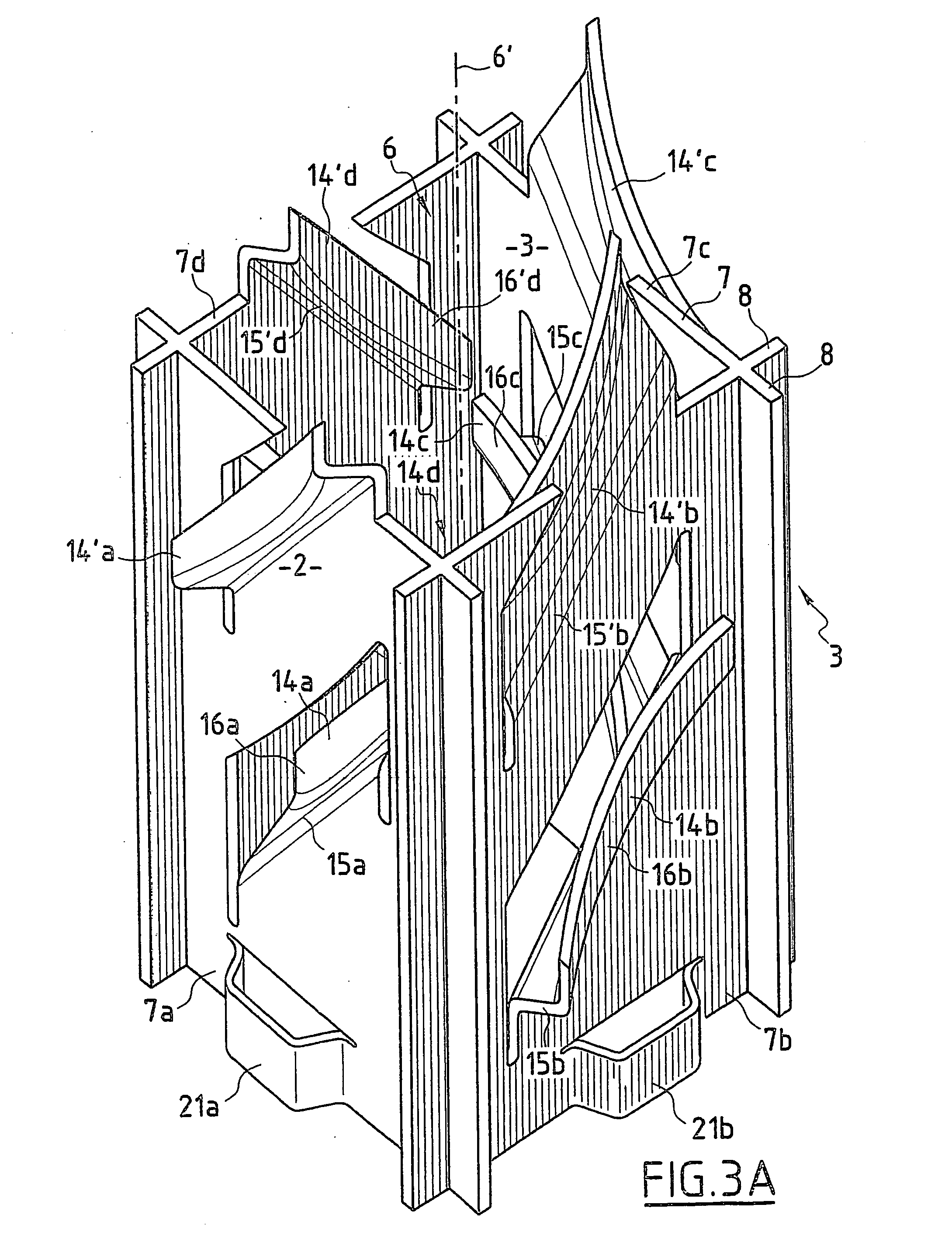
"The invention proposes a spacer grid for a fuel assembly in a nuclear reactor. The grid consists of cells that hold fuel rods in parallel arrangements. The cells have a peripheral wall with an open space between the wall and the fuel rod. The grid includes a helical arrangement of elements that bear on the fuel rod and retain it in a central position. The elements are made of a part of the cell's peripheral wall that is folded and cut in a direction inclined to the cell's axis. The grid is simple in construction, effective in retaining the rods, and can mix cooling water effectively."

Problems solved by technology

Construction of the spacer grids is therefore complex, because they requires many cutting, stamping, fitting and welding operations.
In addition, the six-point retention of the fuel rods inside each of the cells may result in local wear of the rod cladding in contact with the dimples or leaf springs, by friction because the reactor cooling water sets the rods in vibration inside the spacer grids.
This phenomenon, which is generally called “fretting wear”, may result, over long periods of use of the nuclear reactor, in the cladding of the rods being punctured in the contact regions.
Finally, the ability of the vanes cut along the upper edges of the spacer grids to provide mixing is limited, so that perfect temperature homogenization of the cooling water flowing in the fuel assembly is not achieved.
This may result in hot spots in contact with the rods in certain regions, where the boiling crisis phenomenon, that is to say the local formation of vapor bubbles in the cooling water, is observed to occur.

Method used


Image

  • Spacer grid for a fuel unit in a nuclear reactor cooled by light water
  • Spacer grid for a fuel unit in a nuclear reactor cooled by light water
  • Spacer grid for a fuel unit in a nuclear reactor cooled by light water

Examples


Embodiment Construction

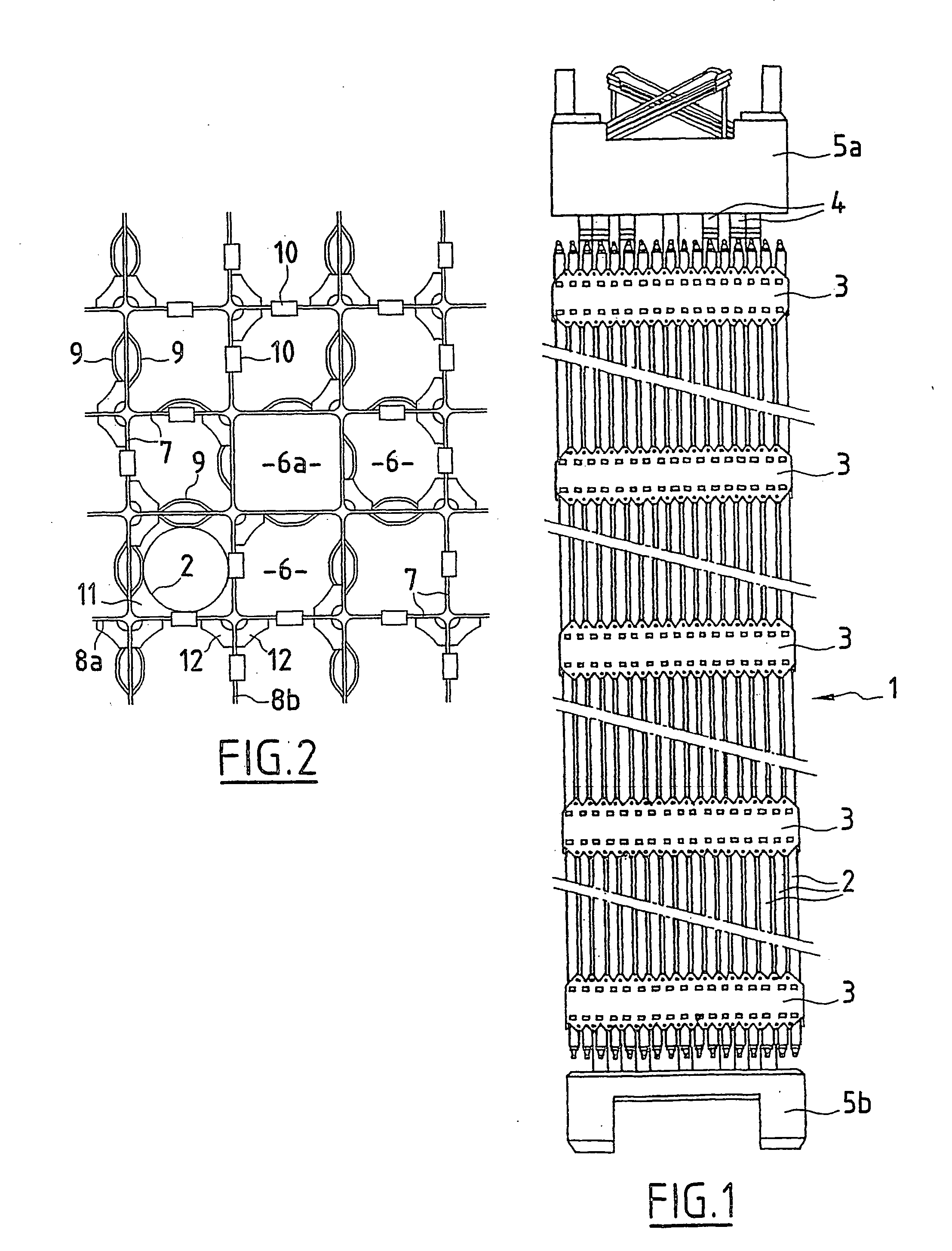
[0023]FIG. 1 illustrates a fuel assembly for a pressurized-water-cooled nuclear reactor, denoted overall by the reference numeral 1.

[0024] The fuel assembly 1 consists of a bundle of substantially cylindrical fuel rods 2 consisting of a metal cladding in which fuel pellets are stacked, the cladding being closed off at its ends by plugs.

[0025] The fuel rods 2 of the fuel assembly bundle are held in place by a framework, which comprises a plurality of spacer grids 3 distributed along the longitudinal direction of the fuel assembly, in the axial direction of the rods 2, guide tubes 4, which are placed inside the bundle of fuel rods 2 and joined to the grids 3, and an upper nozzle 5a and a lower nozzle 5b that are rigidly fastened to the ends of the guide tubes 4, the length of which is greater than the length of the fuel rods 2 of the bundle.

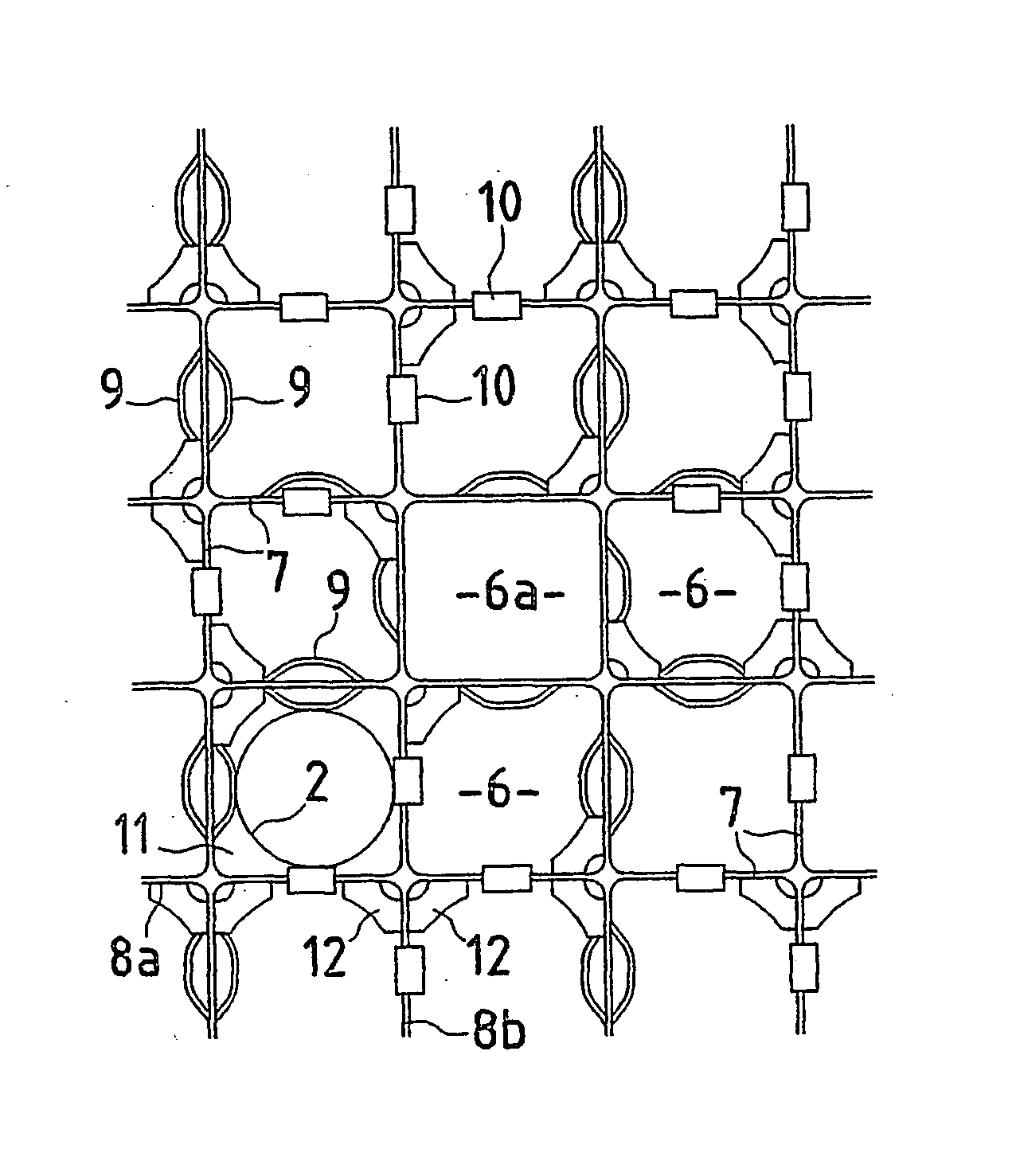
[0026] The spacer grids, which ensure transverse retention of the fuel rods 2 of the fuel assembly bundle, comprise, as can be seen in FIG. 2, ...


PUM


Abstract

A spacer grid for a fuel assembly in a light-water-cooled nuclear reactor, for providing the transverse retention of a bundle of fuel rods in mutually parallel arrangements, having an array of cells juxtaposed and placed in a regular lattice, each bounded and separated from neighboring cells by at least one peripheral wall which is open at two opposed ends, along the direction of an axis of the cell, so as to receive a fuel rod of cylindrical general shape passing along the cell along its axis parallel to the peripheral wall.

Description

FIELD OF THE INVENTION [0001] The invention relates to a spacer grid for a fuel assembly in a light-water-cooled nuclear reactor. BACKGROUND INVENTION [0002] Light-water-cooled nuclear reactors and in particular pressurized-water-cooled nuclear reactors use fuel assemblies comprising a bundle of fuel rods held in place by a framework in mutually parallel arrangements. [0003] The fuel assembly framework comprises, in particular, a plurality of spacer grids distributed along the length of the fuel assembly, in the axial direction of the bundle of rods. The spacer grids ensure transverse retention of the rods and comprise a set of juxtaposed cells arranged in a regular lattice, generally with square lattice cells, the cells themselves having a square cross section in a transverse plane of the spacer grid perpendicular to the axis of the rods. Each of the cells is bounded and separated from the adjacent cells by a peripheral wall having the shape of the lateral surface of a square-based...

Claims


Application Information

Patent Timeline
Patent Type & Authority Applications(United States)
IPC IPC(8): G21C3/322G21C3/356
CPCG21C3/322G21C3/356G21Y2002/101Y02E30/38G21Y2002/302G21Y2004/30G21Y2004/302G21Y2002/201Y02E30/30
Inventor BONNAMOUR, BRUNOBONNAMOUR, MICHELGAUTHIER, JACQUESSALAUN, HUBERT
Owner FRAMATOME ANP
Learn More