Loudspeaker edge

Inactive Publication Date: 2005-10-13
PANASONIC CORP
View PDF12 Cites 14 Cited by
  • Summary
  • Abstract
  • Description
  • Claims
  • Application Information

AI Technical Summary

Problems solved by technology

That is, the results of the studies are not satisfactory about “sectional shape, weight and weight distribution,

Method used


Image

  • Loudspeaker edge
  • Loudspeaker edge
  • Loudspeaker edge

Examples


example 1

(EXAMPLE 1)

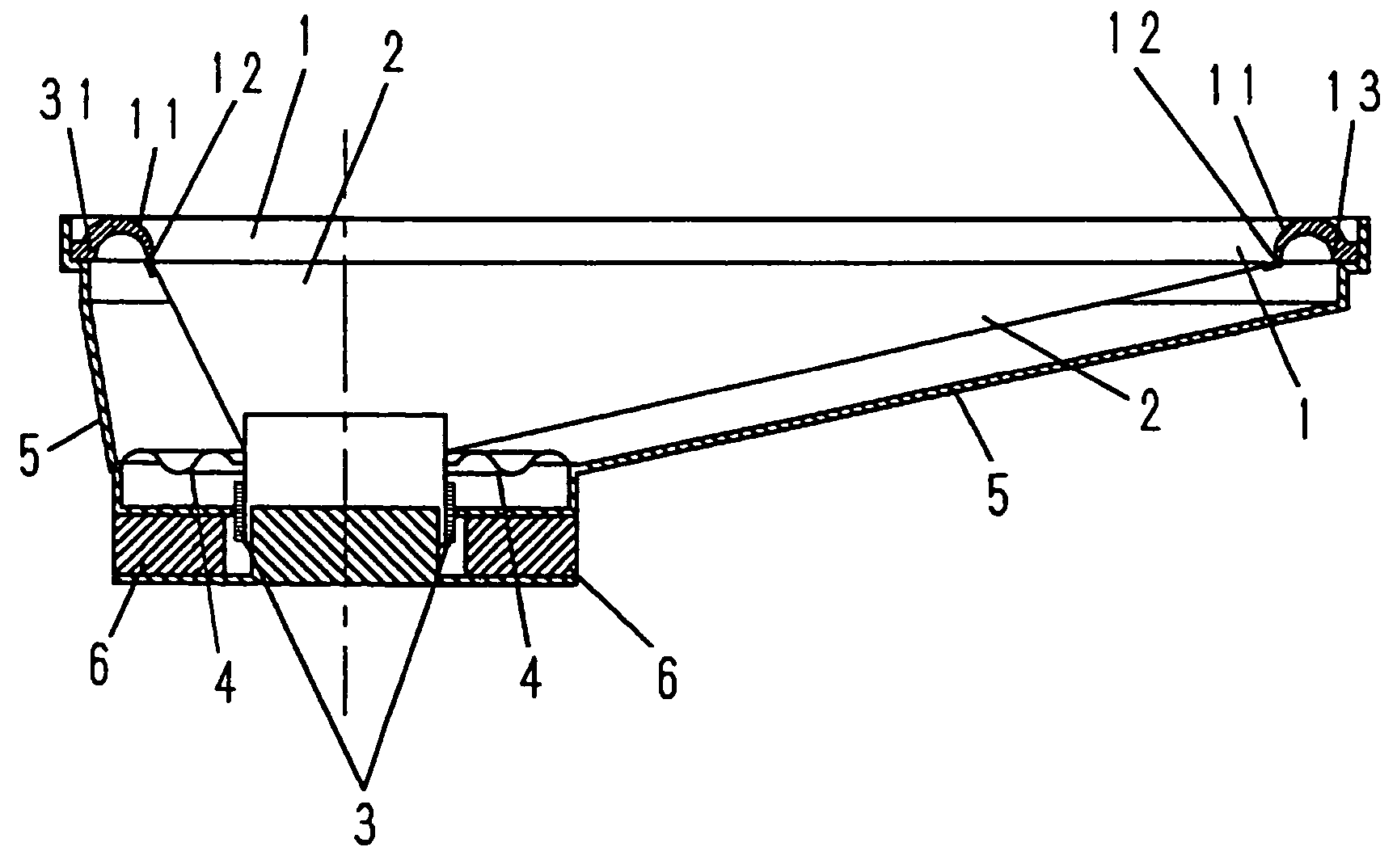
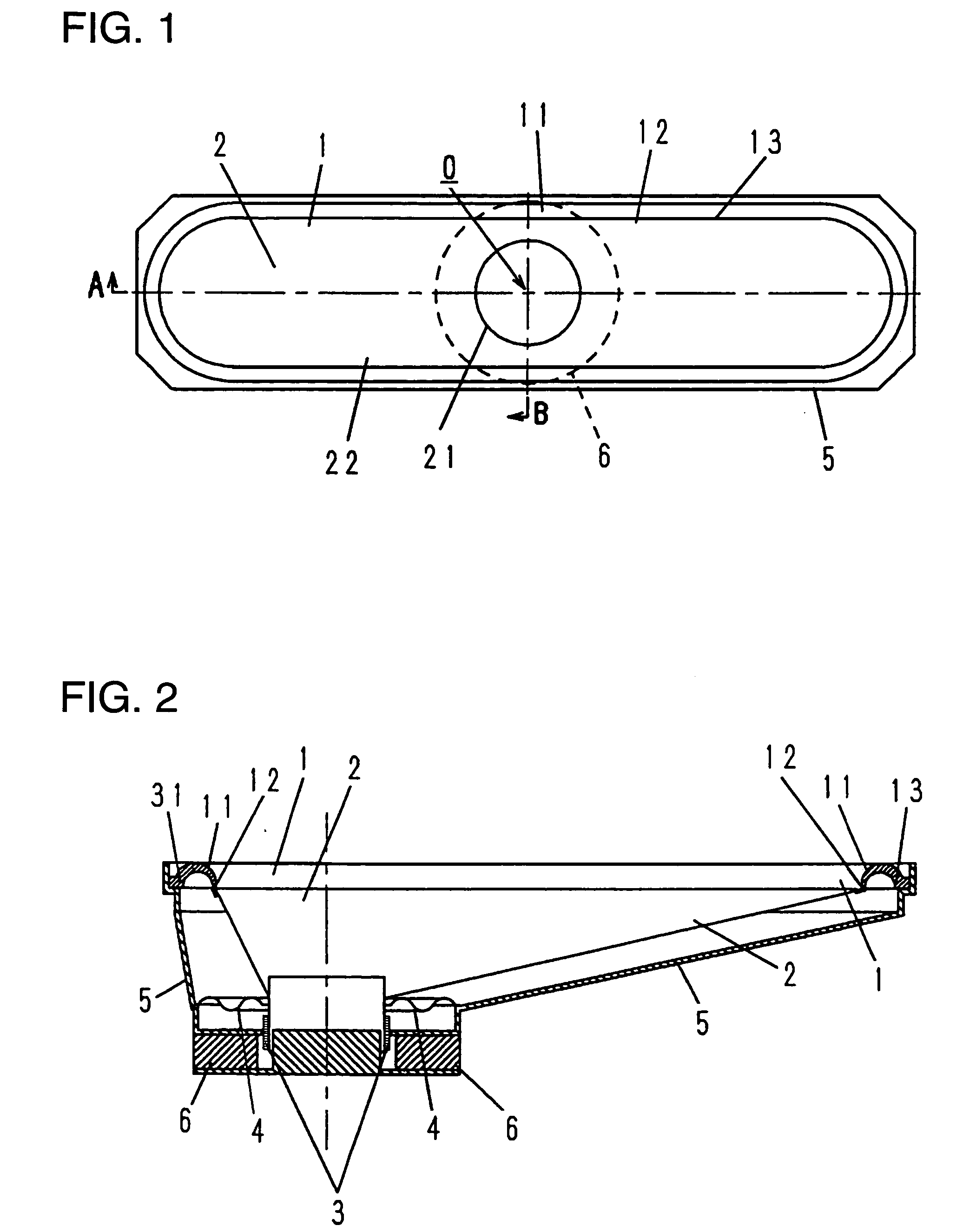
[0032] The first example of the present invention will be described in the following with reference to FIG. 1 and FIG. 2.

[0033]FIG. 1 is a top view of a slim loudspeaker in the first example of the present invention. FIG. 2 shows cross sections of the loudspeaker in two directions of AO (lengthwise direction) and BO (widthwise direction) in FIG. 1. In FIG. 2, magnetic circuit 6 comprises lower plate 6a, ring magnet 6b, and upper plate 6c. An outer periphery of diaphragm 2 is bonded via edge 1 to frame 5 which is bonded to the magnetic circuit 6, and an inner periphery of the diaphragm 2 is bonded to voice coil 3 inserted into magnetic gap 6d of the magnetic circuit 6.

[0034] An outer periphery of damper 4 is bonded to the frame 5, and an inner periphery is bonded to the voice coil 3 to support the voice coil 3.

[0035] When a signal current flows in the voice coil 3, a driving force is generated to vibrate the diaphragm 2, radiating acoustic waves corresponding to a wave ...

example 2

(EXAMPLE 2)

[0043]FIG. 6 is a top view of a slim loudspeaker in accordance another example of the present invention. FIG. 7 is a sectional view of the loudspeaker in two directions of AO and BO in FIG. 6. In the description of the present example, same component parts as those in the example 1 are given same reference numerals, and the description is omitted.

[0044] Edge 1d of the present embodiment is made of foamed resin mainly based on polyurethane resin as the same in Example 1, and its flexible portion is divided into a plurality of sections in a circumferential direction with convex portion 14a and concave portion 14b alternately arranged. Further, the boundary between the adjacent sections crosses the edge id at an angle different from the peripheral direction, and thereby, the shape smoothly changes from convex to concave without abrupt change in shape. In general, a displacement of an edge in a direction of convex and in a direction of concave are reverse in linearity with r...

example 3

(EXAMPLE 3)

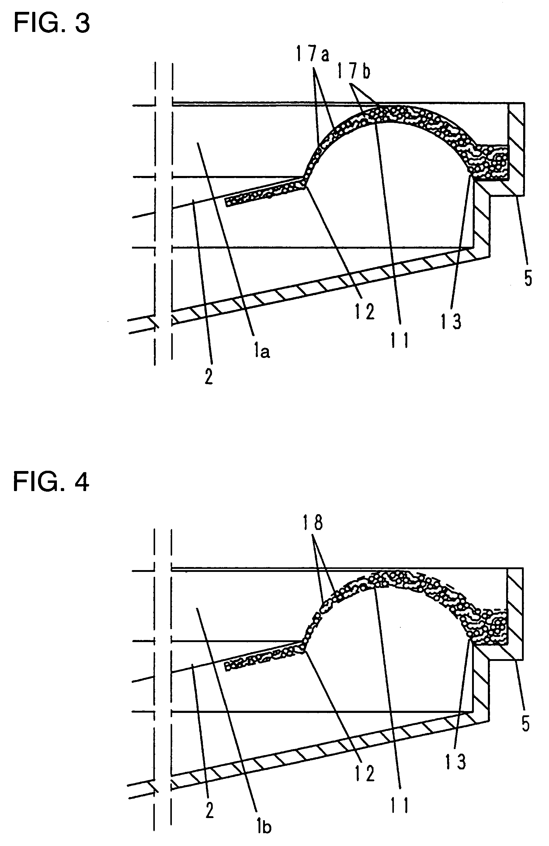
[0047]FIG. 9 is a sectional view in two directions of AO and BO of other loudspeaker having the shape of FIG. 6. In the present Example, a diameter of an inner periphery portion 12 of edge 1 made of foamed resin mainly based on a polyurethane resin as the same in Example 1 is formed smaller than a diameter of an outer periphery 22 of diaphragm 2. In the loudspeaker of the present Example, the diaphragm 2 is supported by the edge 1 with inner portion 23 formed inwardly from the outer periphery 22 thereof. According to the configuration of the present example, in a case where a same maximum dimension of a frame is employed, it is possible to improve a low frequency range sound reproduction and to increase the efficiency by maximizing an effective area of the diaphragm.

[0048]FIG. 10 shows a modification of the present example, showing a sectional view in the same direction as in FIG. 9. As the same in Example 1, the sectional shape in the radial direction of edge 1 made of ...


PUM


Abstract

The present invention provides a loudspeaker which is excellent in acoustic characteristics such as frequency characteristics and distortion characteristics. Particularly, edge 1 is formed in such manner that a thickness of sectional shape in radial direction increases from inner periphery portion 12 toward outer periphery portion 13. Due to this structure, a mechanical impedance of edge 1 against diaphragm 2 is decreased and bad influences on a vibration mode of the diaphragm are suppressed, and also, vibration energy is absorbed by the thick portion of the outer periphery portion, thereby suppressing standing waves of the diaphragm. The structure increases an efficiency of the medium and high frequency range sounds radiated from the loudspeaker, and further, greatly contributes to improve frequency characteristics, nonlinear distortion characteristics, and transient characteristics.

Description

TECHNICAL FIELD [0001] The present invention relates to a loudspeaker mainly used in acoustic apparatus. BACKGROUND ART [0002] Firstly, a conventional loudspeaker is described with reference to FIG. 19 showing a top view of a conventional long shaped loudspeaker (especially, loudspeakers with large length to width ratio in shape, which are hereafter generally recited as “slim loudspeakers”) and FIG. 20 showing a two-directional sectional view in a lengthwise and a widthwise directions of the slim loudspeaker. [0003] Magnetic circuit 6 shown in FIG. 20 comprises lower plate 6a, ring-shaped magnet 6b, and upper plate 6c. Frame 5 is bonded to the magnetic circuit 6. An outer periphery of diaphragm 2 is bonded to the frame 5 via edge 1, and an inner periphery thereof is bonded to voice coil 3 inserted in magnetic gap 6d of the magnetic circuit 6. [0004] An outer periphery of damper 4 is bonded to the frame 5, and an inner periphery is bonded to the voice coil 3 to support the voice coil...

Claims


Application Information

Patent Timeline
IPC IPC(8): H04R1/28H04R5/02H04R7/12H04R7/20H04R7/22
CPCH04R7/12H04R2307/207H04R2307/204H04R7/20H04R7/22
Inventor TABATA, SHINYATANAKA, HIDEKAZU
Owner PANASONIC CORP
Why Eureka
Try Eureka