Microfluidic chip for high-throughput screening and high-throughput assay

a microfluidic chip and high-throughput technology, applied in the direction of fluid speed measurement, positive displacement liquid engine, optical light guide, etc., can solve the problems of inability to analyze a large number of cells at the same time, inability to stably hold cells in place, and high-integration structure that cannot help inject reagents into each individual well independently, so as to achieve easy injection of reagents and improve the degree of integration

Active Publication Date: 2005-10-13
KOREA ADVANCED INST OF SCI & TECH
View PDF6 Cites 14 Cited by
  • Summary
  • Abstract
  • Description
  • Claims
  • Application Information

AI Technical Summary

Benefits of technology

[0009] Another object of the present invention is to provide a micro-fluidic chip, in which wells can be arranged in a two-dimensional pattern and thus a degree of integration can be improved.
[0010] Another object of the present invention is to provide a micro-fluidic chip, in which a specimen or reagent can be is

Problems solved by technology

However, only the highly integrated structure would not help injecting a reagent into each individual well independently.
However, it has disadvantages in that the

Method used


Image

  • Microfluidic chip for high-throughput screening and high-throughput assay
  • Microfluidic chip for high-throughput screening and high-throughput assay
  • Microfluidic chip for high-throughput screening and high-throughput assay

Examples


first embodiment

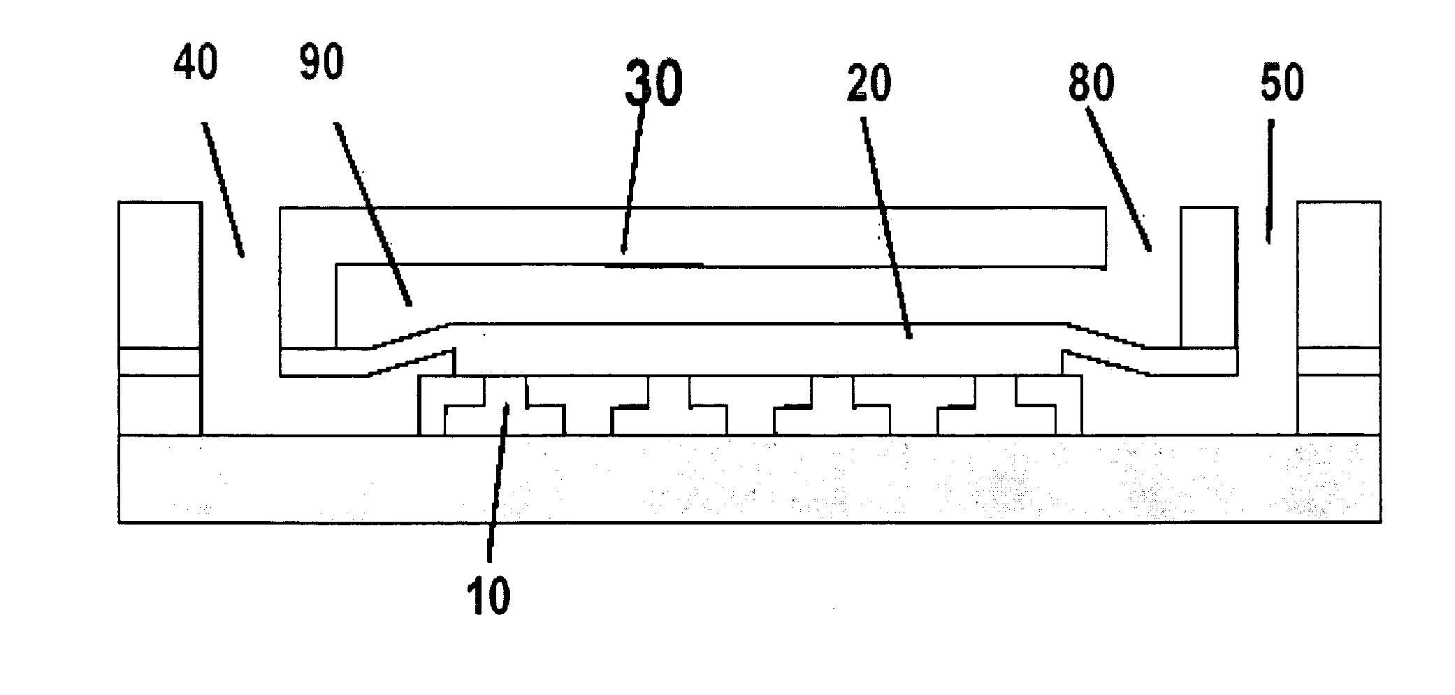
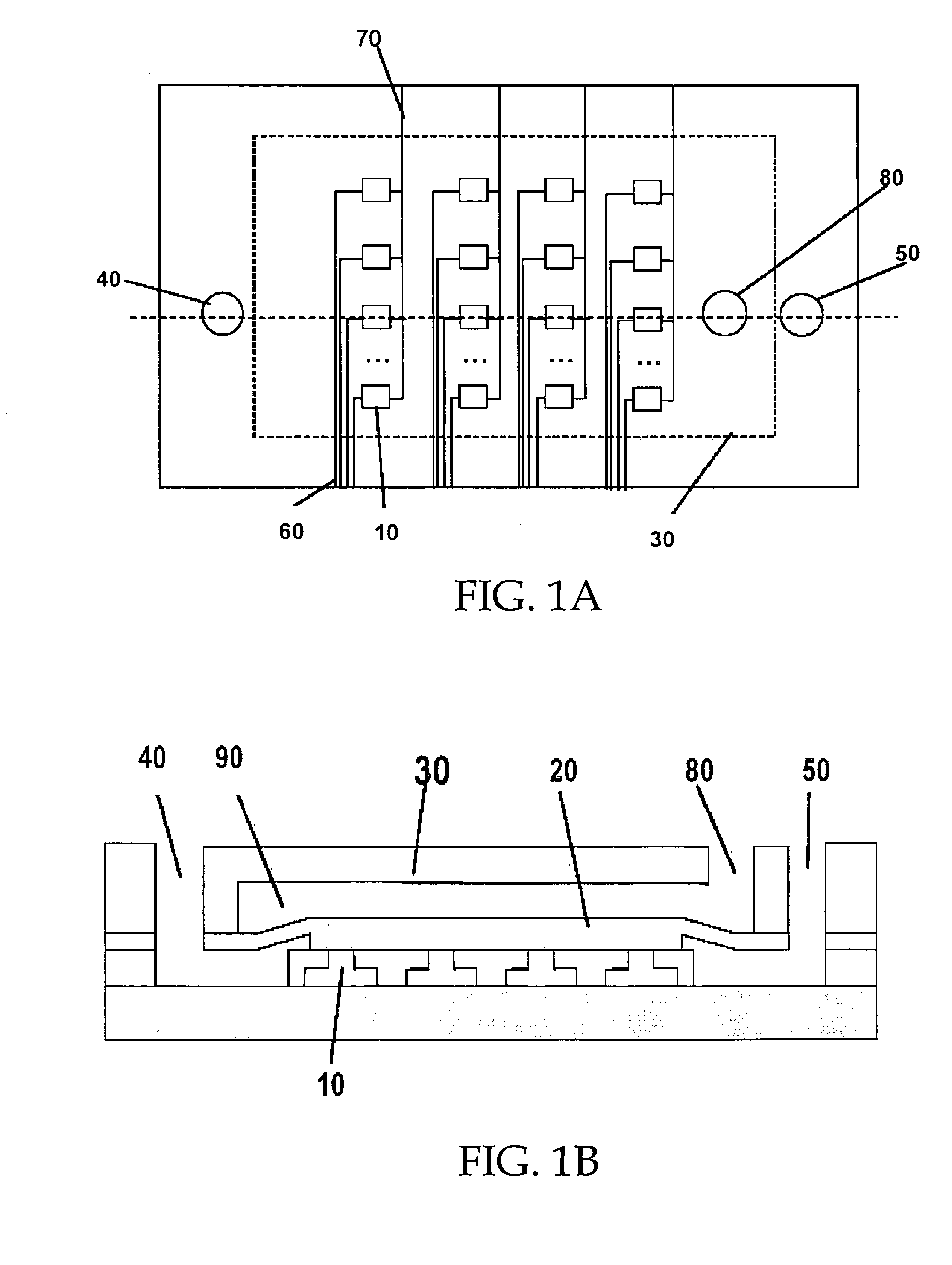
[0024]FIGS. 1a and 1b are respectively a plan view and a cross-sectional view schematically showing a micro-fluidic chip according to the invention.

[0025] As shown in FIGS. 1a and 1b, the micro-fluidic chip comprises a well 10, a specimen isolating means 20, an opening and closing means 30, an inlet 40, an outlet 50, a reagent-injecting passage 60, and a reagent-discharging passage 70.

[0026] The well 10 is arranged in one- or two-dimension, in which a specimen such as a cell, a bead or a solution is placed. Also, a reagent is injected thereto in order to detect a reaction with the specimen.

[0027] In addition, the wells 10 may be extended endlessly in a two-dimensional plane. Furthermore, the two-dimensional arrangement of the wells 10 may be carried out in a patterned or non-patterned fashion.

[0028] Also, the amount or number of isolated specimen to be injected into the well 10 can be varied with the size of the well 10.

[0029] The specimen-isolating means 20 is disposed above th...

second embodiment

[0059] Here, the metal electrode according to the invention may be extended into the outside thereof to thereby form a pad 420, through which an electric signal can be applied or detected.

[0060] The metal electrode 410 is preferred to be formed of one of gold, silver, platinum, aluminum, semiconductor material or conductive polymer.

[0061] The second embodiment of the invention can obtain the same effects as in the first embodiment, by applying in the same way a two-dimensional arrangement, the amount or number of specimen according to the size of the well, the channel of the reagent-injection passage, the reagent to be injected, and the empty space of the isolating means. The detailed explanation of the above application is previously made in conjunction with the first embodiment of the invention, and thus will not be repeated here.

[0062] In addition, similar to the first embodiment, the second embodiment may employ various types of opening and closing means, such as by an air pre...


PUM


Abstract

Disclosed is a micro-fluidic chip for high-throughput screening and high-throughput assay, in which its structure is improved, thereby enhancing the efficiency of high-throughput screening and high-throughput assay. The micro-fluidic chip includes a well for isolating a specimen. The well can be arranged in a one- or two-dimension. A specimen-isolating means is disposed above the well and is movable upwards and downwards. An opening and closing means for moving the specimen-isolating means upwards and downwards is disposed above the specimen-isolating means. An inlet for injection the specimen and an outlet for discharging an excess of the injected specimen are provided. A reagent-injecting passage for injecting a reagent and a reagent-discharging passage for discharging the reagent are also provided.

Description

BACKGROUND OF THE INVENTION [0001] 1. Field of the Invention [0002] The present invention relates to a micro-fluidic chip, particularly to such a chip for high-throughput screening and high-throughput assay, in which its structure is improved, thereby enhancing the efficiency of high-throughput screening and high-throughput assay. [0003] 2. Background of the Related Art [0004] In general, a well plate has been used for biological and chemical experiments. There are a 16-well plate, a 48-well plate or a 96-well plate depending on the number of wells. Recently, a plate having more than 1536 wells has been introduced for a high-throughput assay. [0005] Further, the advancement in micro-machining technique facilitates the development of micro-fluidic chips for a high-throughput assay. U.S. Pat. No. 6,235,520 B1 discloses a micro-fluidic chip having a high degree of integration. However, only the highly integrated structure would not help injecting a reagent into each individual well ind...

Claims


Application Information

Patent Timeline
IPC IPC(8): G01N35/08B01L3/00B81B1/00G01N33/483G01N33/50G01N37/00
CPCB01L3/5025B01L3/502761B01L2200/0668B01L2400/0487B01L2300/0877B01L2400/0424B01L2300/0816E02B3/129E02D29/0283E02D2600/20
Inventor YUN, KWANG-SEOKYOON, EUI SIK
Owner KOREA ADVANCED INST OF SCI & TECH
Why Eureka
Try Eureka