Flue gas treating equipment

a technology of flue gas treatment and exhaust gas, which is applied in the direction of lighting and heating equipment, combustion types, separation processes, etc., can solve the problems of deteriorating toxicity elimination performance, affecting the flow and combustion state of exhaust gas, and affecting the efficiency of exhaust gas scraping and removal, so as to achieve the effect of easy scraping and removal

Inactive Publication Date: 2005-10-13
KOIKE SANSO KOGYO CO LTD
View PDF8 Cites 13 Cited by
  • Summary
  • Abstract
  • Description
  • Claims
  • Application Information

AI Technical Summary

Benefits of technology

[0013] The present invention has been accomplished to solve the above problems, and it is a first object of the invention to provide an exhaust gas processing apparatus capable of more effectively scraping off powder which is attached to an inner surface of a combustion chamber, and capable of increasing lifetime of an impact member which generates an impact against a scraping member. It is a second object of the invention to provide an exhaust gas processing apparatus capable of scraping off powder in a sate in which the scraping member is reliably in contact with the inner surface of the combustion chamber over a direction in which exhaust gas passes through the combustion chamber.
[0016] The blade portion or the acute edge portion is provided on the lever constituting the scraping member at the position opposed to the inner surface of the combustion chamber. Thus, the surface of the lever which scrapes off the powder can have the acute angle with respect to the inner surface of the combustion chamber. With this, the scraping member can effectively scrape off the powder attached to the inner surface of the combustion chamber, and the inside of the combustion chamber can be cleaned.
[0017] The apparatus has an impact member for generating an impact against the scraping member, and a plurality of leaf springs overlapped on one another with steps therebetween for generating an impact as the impact member bends the lever when the impact member comes into contact with the lever and the lever is returned to its original shape when the contact is released. With this, the stress applied to the leaf spring can be made surface contact and with this, the stress applied to the leaf spring can be moderated and the bending can be prevented, and the lifetime of the impact member can be increased.
[0020] With this configuration, the scraping member can move in the direction in which the exhaust gas flows through the combustion chamber along the inner surface of the combustion chamber by the driving member provided outside of the combustion chamber. Therefore, the scraping member can scrape off powder along the inner surface of the combustion chamber in a state in which the scraping member is reliably in contact with the inner surface in the direction in which the exhaust gas flows through the combustion chamber, and powder strongly attached to the inner surface of the combustion chamber can easily be scraped off and removed.

Problems solved by technology

Since such toxic exhaust gas is highly harmful to human body, it is required to completely remove the toxic material when the exhaust gas is discharged into atmosphere.
For example, when powder is generated in a combustion chamber and the powder is accumulated on the cylindrical inner surface constituting the exhaust gas supply passage and the combustion section, this adversely affects the flow and the combustion state of the exhaust gas, and there is an adverse possibility that the toxicity eliminating performance is deteriorated.
Thus, maintenance for removing the powder, and this fact deteriorates the efficiency.
However, when the scraper is a flat bar, since a surface thereof which scrapes off powder attached to the inner surface of the cylindrical body is substantially perpendicular to the inner surface of the cylindrical body, the powder can not be scraped off effectively, and there is a problem that the power attaches to the inner surface of the cylindrical body strongly.
However, when the fixing location of the leaf spring is a point or line contact, there is a problem that when the leaf spring is bent, the fixing location is prone to be folded.
Since one side of the scraper is supported, it is difficult to scrape the powder in a state in which a tip end of the scraper is reliably in contact with the inner surface of the cylindrical body.

Method used


Image

  • Flue gas treating equipment
  • Flue gas treating equipment
  • Flue gas treating equipment

Examples


Embodiment Construction

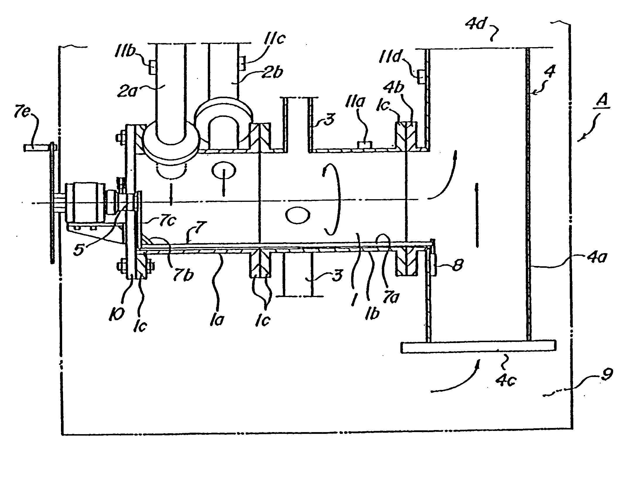
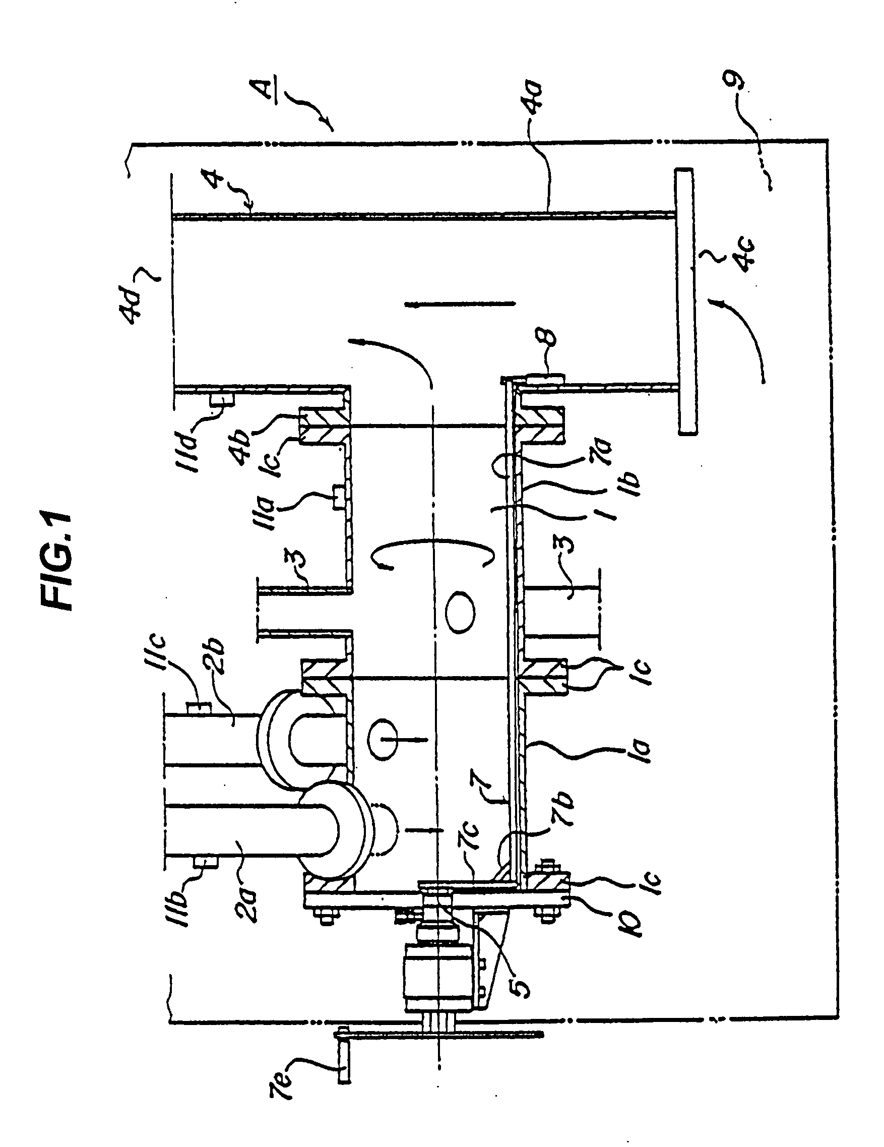
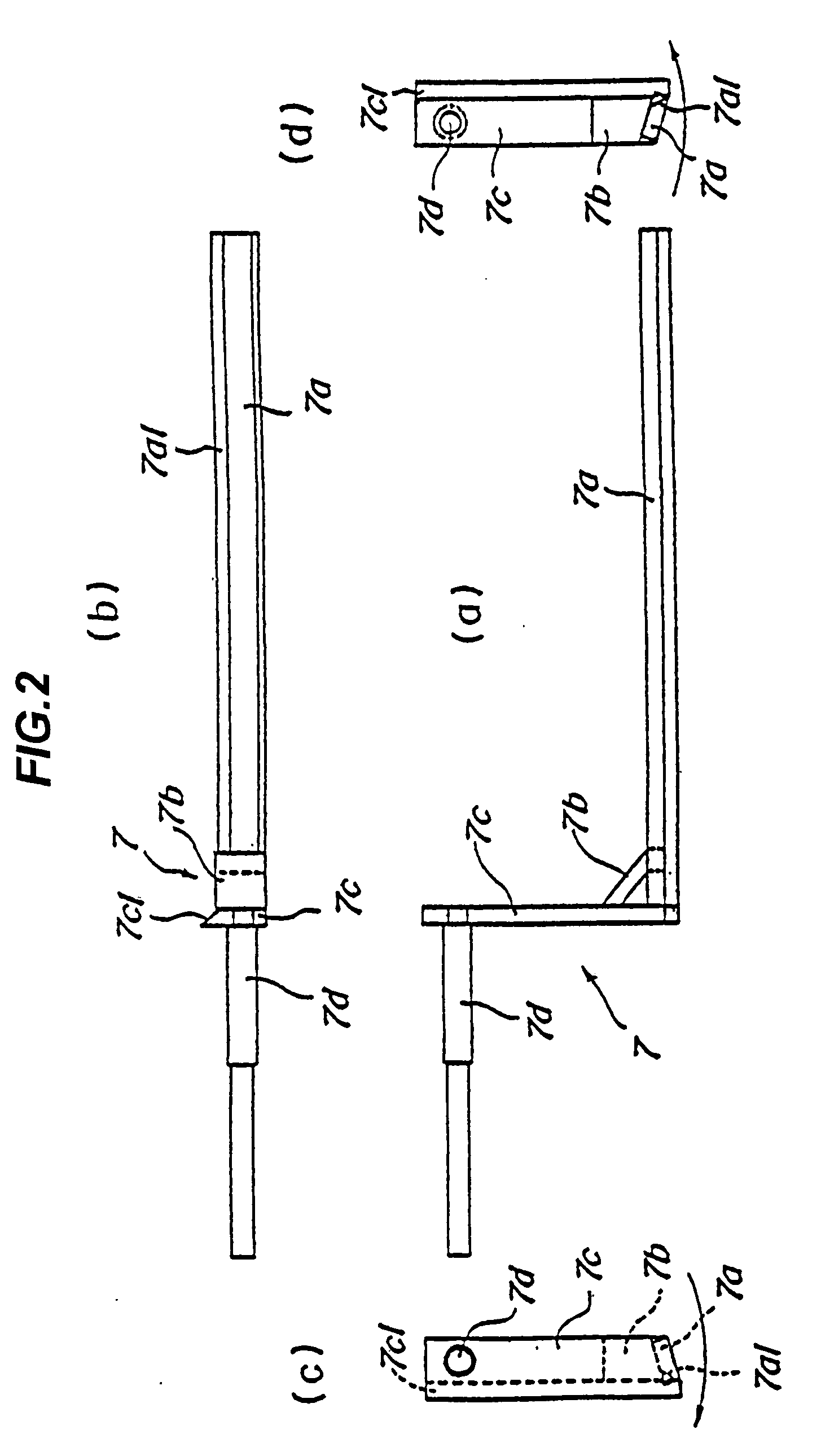
[0026] One embodiment of an exhaust gas processing apparatus of the present invention will be explained concretely using the drawings. FIG. 1 is a perspective explanatory view showing a configuration of a first embodiment of an exhaust gas processing apparatus according to the present invention. FIG. 2(a) is a front view showing a configuration of a scraping member of the first embodiment, FIG. 2(b) is a plan view showing the configuration of the scraping member of the first embodiment, FIG. 2(c) is a left side view showing the configuration of the scraping member of the first embodiment and FIG. 2(d) is a right side view showing the configuration of the scraping member of the first embodiment. FIG. 3 is an explanatory view of an angle of a blade portion or an acute edge portion of the scraping member of the first embodiment. FIG. 4 is a sectional explanatory view showing a configuration of an impact member of the first embodiment.

[0027] A configuration of a first embodiment of the...


PUM


Abstract

It is an object of the present invention to provide an exhaust gas processing apparatus capable of more effectively scraping off powder which is attached to an inner surface of a combustion chamber, and capable of increasing lifetime of an impact member which generates an impact against a scraping member. The exhaust gas processing apparatus is characterized in that a blade portion or an acute edge portion 7a1 is provided on a lever 7a which is a scraping member at a position opposed to an inner surface of a combustion chamber 1. The scraping member moves in a circumferential direction along the inner surface of the combustion chamber 1 to scrape off powder which is attached to the inner surface of the combustion chamber 1.

Description

TECHNICAL FIELD [0001] The present invention relates to an exhaust gas processing apparatus for burning exhaust gas which is used and discharged during production of semiconductors and which includes flammable gas component and burning gas component, thereby rendering the exhaust gas harmless. BACKGROUND ART [0002] It is known that harmful exhaust gas such as silane (SiH4), disilane (Si2H6), diborane (B2H6), phosphine (PH3), arsine (AsH3) and nitrogen trifluoride (NF3) is produced during the producing procedure of semiconductors. Since such toxic exhaust gas is highly harmful to human body, it is required to completely remove the toxic material when the exhaust gas is discharged into atmosphere. [0003] Exhaust gas of flon gas which affects global environment such as carbon tetrafluoride (CF4) is produced in other particular procedure in the semiconductor producing procedure. It is required to eliminate such exhaust gas when discharged into atmosphere. [0004] For example, Japanese Pa...

Claims


Application Information

Patent Timeline
Patent Type & Authority Applications(United States)
IPC IPC(8): B01D53/46F23G7/06F23J1/06F23J1/00
CPCF23J1/06H01L21/02
Inventor PARK, BYOUNG-SUPJIN, BINGZHE
Owner KOIKE SANSO KOGYO CO LTD
Why Eureka
Try Eureka