
Magnetic recording medium and magnetic storage apparatus

Inactive Publication Date: 2005-10-13
SHOWA DENKO KK
View PDF18 Cites 6 Cited by
  • Summary
  • Abstract
  • Description
  • Claims
  • Application Information

AI Technical Summary

Benefits of technology

[0027] Accordingly, it is a general object of the present invention to provide a novel and useful magnetic recording media and magnetic storage apparatuses, in which the problems described above are eliminated.
[0028] Another and more specific object of the present invention is to provide a magnetic recording medium and a magnetic storage apparatus, which can reduce grain sizes of a magnetic recording layer, promote desired orientation of the magnetic recording layer, and realize an improved performance, at a relatively low cost.
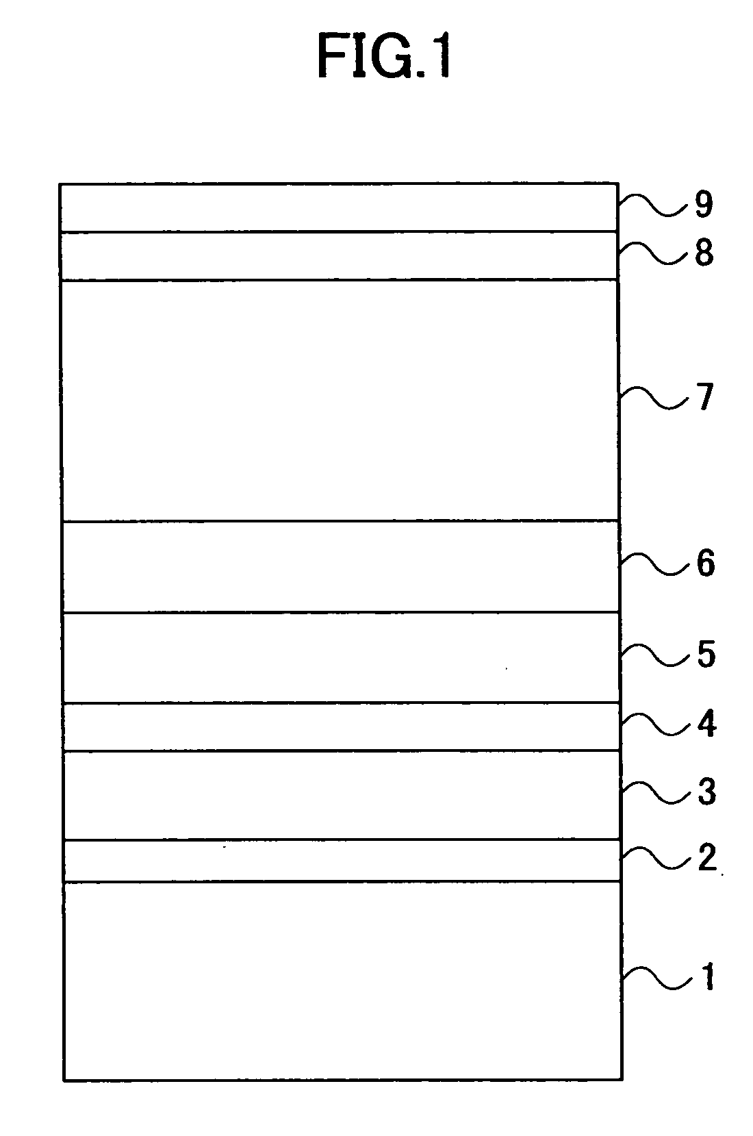
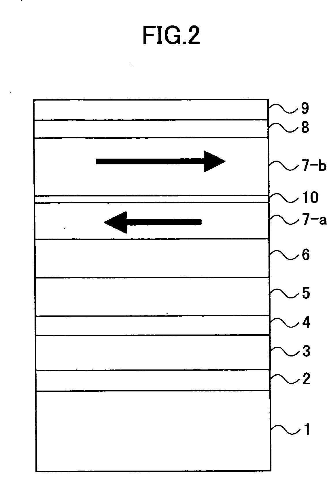
[0029] Still another object of the present invention is to provide a magnetic recording medium comprising a seed layer made of one of AlRu and AlV, a magnetic recording layer made of a CoCr alloy, and an underlayer made of the other of AlRu and AlV, where the underlayer is disposed between the seed layer and the magnetic recording layer. According to the magnetic recording medium of the present invention, it is possible to reduce grain sizes of a magnetic recording layer, promote desired orientation of the magnetic recording layer, and realize an improved performance, at a relatively low cost.
[0030] A further object of the present invention is to provide a magnetic storage apparatus comprising at least one magnetic recording medium comprising a seed layer made of one of AlRu and AlV, a magnetic recording layer made of a CoCr alloy, and an underlayer made of the other of AlRu and AlV and disposed between the seed layer and the magnetic recording layer; and a head which writes information on and / or reproduces information from the magnetic recording medium. According to the magnetic storage apparatus of the present invention, it is possible to reduce grain sizes of a magnetic recording layer, promote desired orientation of the magnetic recording layer, and realize an improved performance, at a relatively low cost.

Problems solved by technology

To achieve an average grain size less than 8 nm is difficult as further reduction of the underlayer thickness results in degradation of the magnetic layer c-axis in-plane orientation (IPO).
However, adding very high percentage of B increases the fct phase and hence the crystallographic quality goes bad beyond a certain B percentage, especially over B concentration of 8%.
Previous work on using NiAl directly on glass as a seed layer for conventional magnetic recording media resulted in poor squareness (h>0.25) and could not match the performance of magnetic recording media on Cr(002) / NiP.
Moreover, as throughput has to be maintained at a high level, the thickness of the deposited film is limited typically to 30 nm.
Since the Ru content is large, the cost of the target is very high.

Method used


Image

  • Magnetic recording medium and magnetic storage apparatus
  • Magnetic recording medium and magnetic storage apparatus
  • Magnetic recording medium and magnetic storage apparatus

Examples


first embodiment

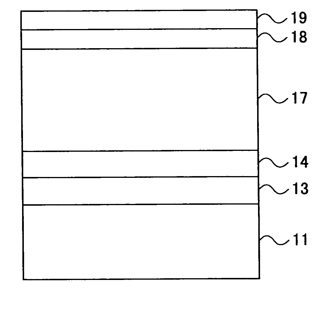
[0054]FIG. 4 is a cross sectional view showing an important part of a magnetic recording medium according to the present invention. In FIG. 4, on a glass or Al substrate 11 is deposited a seed layer 13 and an underlayer 14 which are made of intermetallic alloys. The seed layer 13 may be reactively sputtered with N2 in an Ar+N2 gas mixture or O2 in an Ar+O2 gas mixture at a suitable partial pressure, for example. On the underlayer 14 is deposited a magnetic recording layer (hereinafter simply referred to as a magnetic layer) 17 made of a Co alloy or a CoCr alloy. The magnetic layer 17 has a (11{overscore (2)}0) crystallographic orientation, and may be made up of a single layer or multiple layers that are in direct contact and behave magnetically as one magnetic layer. On the magnetic layer 17, a protective layer 18 made of C, and an organic lubricant layer 19 are deposited for use with a magnetic transducer such as a spin-valve head.

[0055] The glass or Al substrate 11 may be mechanic...

second embodiment

[0062]FIG. 5 is a cross sectional view showing an important part of the magnetic recording medium according to the present invention. In FIG. 5, those parts which are the same as those corresponding parts in FIG. 4 are designated by the same reference numerals, and a description thereof will be omitted.

[0063] In FIG. 5, a seed layer 13 is reactively sputtered with N2 in an Ar+N2 gas mixture or with O2 in an Ar+O2 gas mixture, with a N2 or O2 partial pressure PN,O=1% to 20%. The metal nitride or oxide seed layer 13 promotes an excellent crystallographic orientation for the underlayer 14 and provides excellent (002) growth for Cr based subsequent layers and very good (11{overscore (2)}0) texture for the magnetic layer 17. Hence, this seed layer 13 improves the IPO significantly from the first embodiment described above.

third embodiment

[0064]FIG. 6 is a cross sectional view showing an important part of the magnetic recording medium according to the present invention. In FIG. 6, those parts which are the same as those corresponding parts in FIG. 4 are designated by the same reference numerals, and a description thereof will be omitted.

[0065] In FIG. 6, a plurality of magnetic layers 17-a and 17-b that are antiferromagnetically coupled through a Ru spacer layer 20 to form the so-called synthetic ferrimagnetic medium (SFM) structure. Furthermore, a lattice matching layer 15 may be disposed between the magnetic layer structure (17-a, 17-b) and the underlayer 14 for lattice matching with the magnetic layer structure (17-a, 17-b) and prevention of diffusion from the underlayer 14 into the magnetic layer structure (17-a, 17-b). An hcp interlayer 16 may be inserted between the magnetic layer structure (17-a, 17-b) and the underlayer 14. The hcp interlayer 16 also serves as a buffer between the bcc underlayer 14 and the hc...


PUM


Abstract

A magnetic recording medium includes a seed layer made of one of AlRu and AlV, a magnetic recording layer made of a CoCr alloy, and an underlayer made of the other of AlRu and AlV, where the underlayer is disposed between the seed layer and the magnetic recording layer.

Description

BACKGROUND OF THE INVENTION [0001] This application is a continuation application filed under 35 U.S.C. 111(a) claiming the benefit under 35 U.S.C. 120 and 365(c) of a PCT International Application No.PCT / JP2003 / 006081 filed May 15, 2003, in the Japanese Patent Office, the disclosure of which is hereby incorporated by reference. [0002] The PCT International Application No.PCT / JP2003 / 006081 was published in the English language on Nov. 25, 2004 under International Publication Number WO 2004 / 102539 A1. [0003] 1. Field of the Invention [0004] The present invention generally relates to magnetic storage media and magnetic storage apparatuses, and more particularly to a longitudinal magnetic recording medium having a seed layer and suited for a high-density recording, and to a magnetic storage apparatus which uses such a magnetic recording medium. [0005] 2. Description of the Related Art [0006] A typical longitudinal magnetic recording medium includes a substrate, a seed layer, a Cr or Cr...

Claims


Application Information

Patent Timeline
IPC IPC(8): G11B5/66G11B5/73
CPCG11B5/732G11B5/66G11B5/7379G11B5/676
Inventor AJAN, ANTONY
Owner SHOWA DENKO KK
Learn More