Wire press-clamping method

a wire press and wire technology, applied in the direction of coupling contact members, contact members penetrating/cutting insulation/cable strands, coupling device connections, etc., can solve the problems of low breaking strength of aluminum conductor, inability to withstand an applied force, and cutting of aluminum conductors, etc., to achieve accurate mounting operation, simple connection operation, and easy operation

Active Publication Date: 2005-10-13
YAZAKI CORP
View PDF11 Cites 40 Cited by
  • Summary
  • Abstract
  • Description
  • Claims
  • Application Information

AI Technical Summary

Benefits of technology

[0052] According to the invention, when the press-clamping member is press-clamped to the conductor after the conductor is received in the press-clamping member, the area of contact between the conductor and the press-clamping member is increased by the serrations disposed perpendicular to the axis of the press-clamping member, and therefore the electrical resistance, developing between the conductor and the press-clamping member, is decreased to a lower level.
[0053] According to the invention, when the press-clamping member is to be mounted on the press-clamping terminal, the press-clamping member is inserted into the groove portion, formed by the conductor press-clamping portion and the conductor press-fastening piece portions, from the upper side, and the conductor of the wire is inserted into the press-clamping member from the upper side. Therefore, the connection of the wire to the press-clamping member is effected from one direction, that is, from the upper side, and therefore this connecting operation is simple, and can be easily effected in an automated manner.
[0054] According to the invention, when the press-clamping member is mounted on the press-clamping terminal, the retaining portion is retainingly engaged with the conductor press-fastening piece portions, and therefore the press-clamping member is mounted on the press-clamping terminal in positioned relation thereto. Therefore, any skill is not required for mounting the press-clamping member on the press-clamping terminal, and this mounting operation can be accurately carried out without inviting a mounting error.
[0055] According to the invention, the press-clamping member, covering the conductor of the wire, is mounted on the press-clamping terminal, and the press-clamping member, covering the conductor, increases the pressure of contact between the press-clamping terminal and the conductor, and the area of contact increases, so that the electrical resistance decreases. Thus, the electrical resistance is decreased by increasing the contact area, and therefore the electrical performance is stabilized, so that the product of high quality is obtained.
[0056] According to the invention, the press-clamping member, covering the conductor and the portion of the sheath of the wire, is mounted on the press-clamping terminal, and the press-clamping member, covering the conductor and the portion of the sheath, increases the pressure of contact between the press-clamping terminal and the conductor, and the area of contact increases, so that the electrical resistance decreases. At this time, the conductor press-fastening piece portions are press-fastened to the press-clamping member, and therefore are electrically connected thereto, and also the sheath press-fastening piece portions are press-fastened to the press-clamping member, and therefore are electrically connected thereto. Therefore, the contact area is increased, so that the electrical resistance decreases, and therefore the electrical performance is stabilized, so that the product of high quality is obtained.
[0057] The wire press-clamping method of the invention can solve the problem that the contact area is decreased, so that the electrical resistance increases, and therefore by decreasing the electrical resistance by the increased contact area, there is achieved an advantage that the electrical performance is stabilized, so that the product of high quality can be obtained.

Problems solved by technology

However, the aluminum conductor is lower in breaking strength than the copper conductor, and therefore there is a fear that the aluminum conductor cannot withstand an applied force when a wire harness is assembled.
Namely, there is a fear that the aluminum conductor is cut during the press-fastening (press-clamping) operation since the aluminum conductor is relatively low in strength, and therefore it is desired that the aluminum conductor will not be squeezed during the press-fastening operation.
However, unless the aluminum conductor is adequately squeezed, there arises a problem that the area of contact of the conductor decreases, so that the electrical resistance increases.
Therefore, when the conductors 74 and 86 in the above Patent Literatures 1 and 2 are made of aluminum, there is countered a problem that the area of contact of the conductor decreases, so that the electrical resistance increases, which makes it difficult to flow an electric current of a predetermined value through the wire.

Method used


Image

  • Wire press-clamping method
  • Wire press-clamping method
  • Wire press-clamping method

Examples


first embodiment

[0070] (First Embodiment)

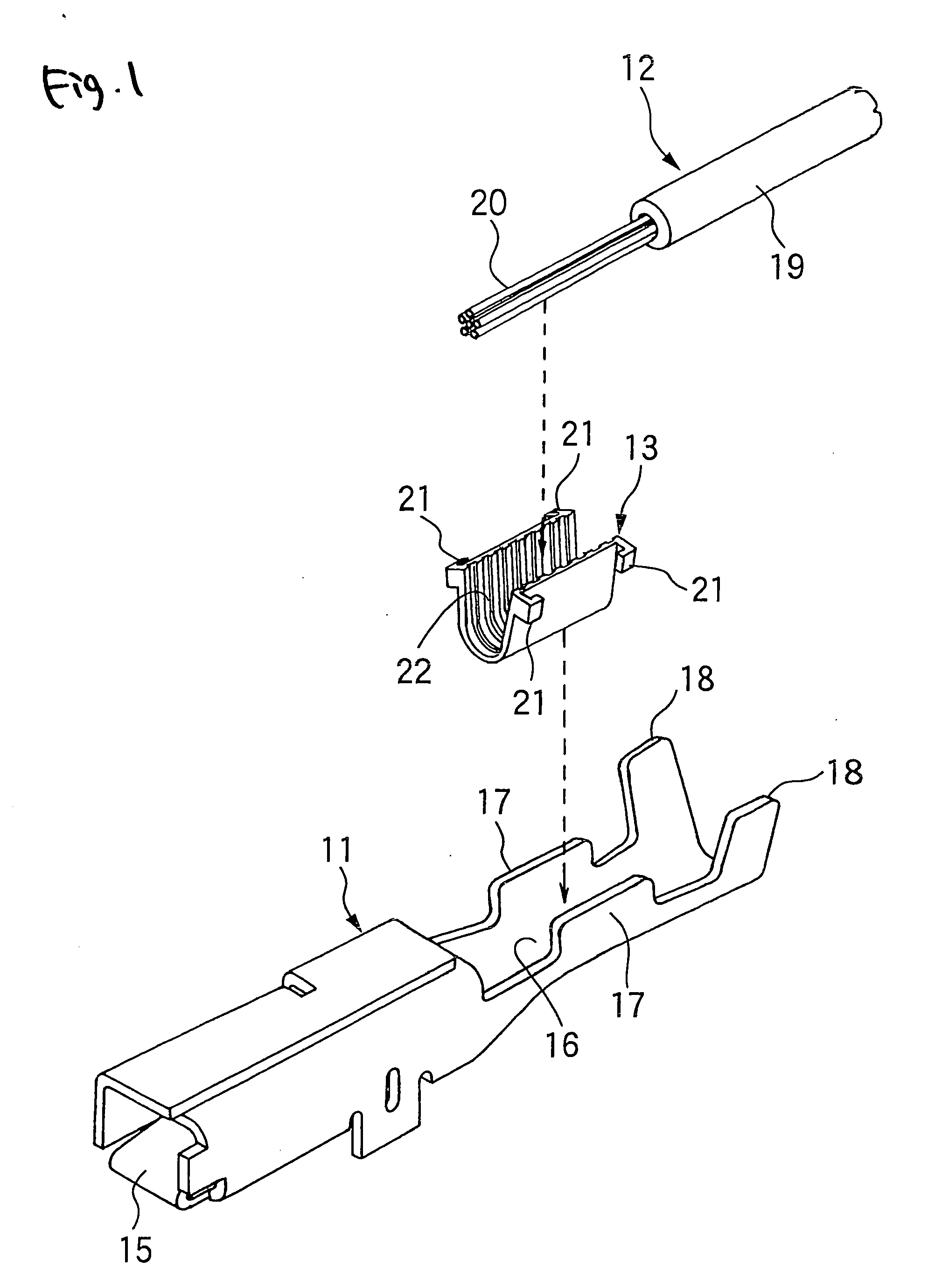
[0071] As shown in FIG. 1, the first embodiment of the wire press-clamping method of the invention is designed to form the terminal-connected wire 14 (shown in FIG. 3), using the press-clamping terminal 11, a wire 12 and the press-clamping member 13.

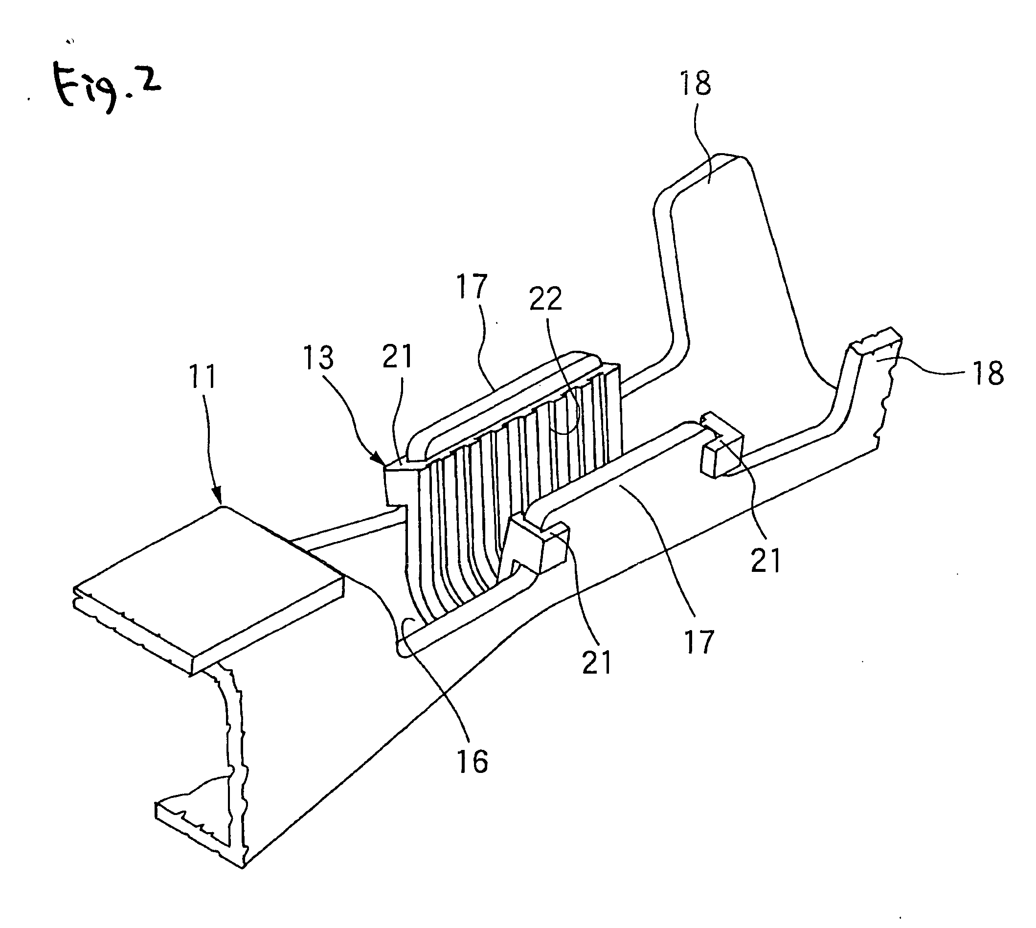
[0072] The press-clamping terminal 11 is formed by bending a sheet of an electrically-conductive material, and this terminal 11 includes an electrical connecting portion 15 formed at one end portion thereof, a conductor press-clamping portion 16 and conductors press-fastening piece portions 17 which are formed at a central portion thereof, and sheath press-fastening piece portions 18 and 18 formed at the other end portion thereof. The electrical connecting portion 15 is formed into a male type or a female type, and is adapted to be electrically connected to a mating terminal of the female or the male type. The conductor press-clamping portion 16 has a U-shape transverse cross-section, and the pair of conductor p...

second embodiment

[0085] (Second Embodiment)

[0086] Next, the second embodiment of the invention will be described with reference to FIGS. 4 to 6. In each of the second and subsequent embodiments, those members, etc., similar in construction and function to the already-described members, etc., will be designated by identical or like reference numerals in the drawings, and explanation thereof will be made briefly or omitted.

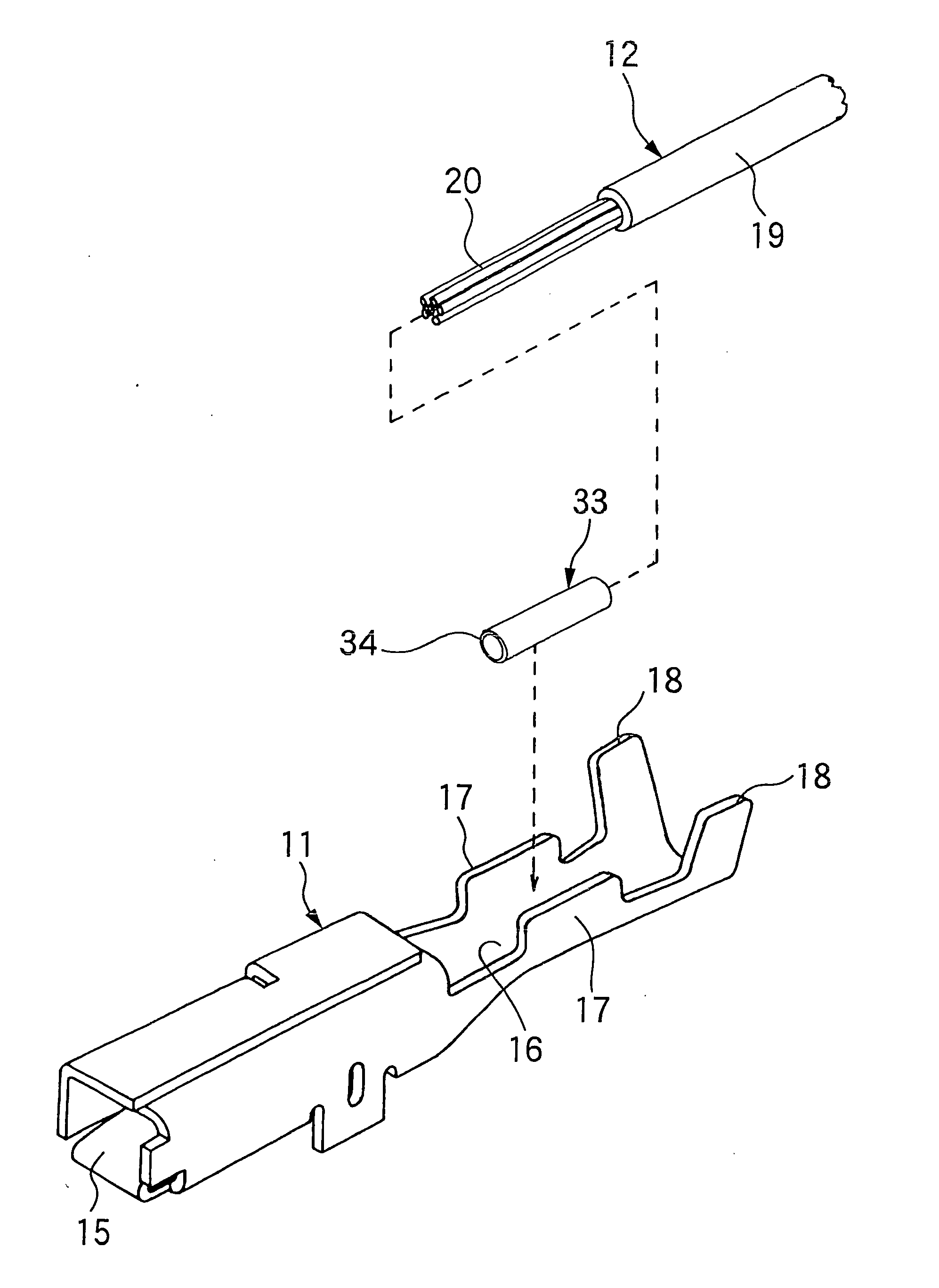
[0087] As shown in FIG. 4, the wire press-clamping method of the second embodiment is designed to form the terminal-connected wire 44 (shown in FIG. 6), using a press-clamping terminal 11, a wire 12 and the press-clamping member 33.

[0088] The press-clamping member 33 is made of an electrically-conductive copper alloy, and includes a tubular body 34 for the passage of a conductor 20 of the wire 12 therethrough, the tubular body 34 being in the form of a cylinder having a thin peripheral wall. The press-claming member 33 has such an outer diameter as to be inserted or fitted into a ...

third embodiment

[0093] (Third Embodiment)

[0094] Next, the third embodiment of the invention will be described with reference to FIGS. 7 to 9.

[0095] As shown in FIG. 4, the wire press-clamping method of the third embodiment is designed to form the terminal-connected wire 64 (shown in FIG. 9), using a press-clamping terminal 11, a wire 12 and the press-clamping member 53.

[0096] The press-clamping member 53 is made of an electrically-conductive copper alloy, and this press-clamping member 53 of an integral construction includes a first tubular portion 54 for the passage of a conductor 20 of the wire 12 therethrough, and a second tubular portion 55 for covering a sheath 19 of the wire 12, each of the first and second tubular portions 54 and 55 being in the form of a cylinder having a thin peripheral wall. The first tubular portion 54 of the press-claming member 53 has such an outer diameter as to be inserted or fitted into a groove portion formed by a conductor press-clamping portion 16 and conductor...


PUM


Abstract

In a wire press-clamping method of press-clamping a conductor of a wire to a conductor press-clamping portion of a press-clamping terminal in electrically-connected relation thereto, there is used the press-clamping terminal having conductor press-fastening piece portions for press-fastening the conductor, and a press-clamping member is interposed between the conductor press-clamping portion and the conductor, and is press-fastened by the conductor press-fastening piece portions.

Description

BACKGROUND OF THE INVENTION [0001] This invention relates to a wire press-clamping method for press-clamping a conductor of a wire to a press-clamping terminal. [0002] There is known one related wire press-clamping method for press-clamping a conductor of a wire to a press-clamping terminal, in which an electrically-conductive member is provided (see, for example, Patent Literature 1). [0003] As shown in FIG. 10, the press-clamping terminal 70, disclosed in Patent Literature 1, includes an electrical contact portion 71, and a wire press-clamping portion 72. The wire press-clamping portion 72 includes a conductor press-clamping portion 75 for press-clamping the conductor 74 of the wire 73, and a sheath press-clamping portion 77 for press-clamping a sheath 76 of the wire 73. The narrow electrically-conductive member 78 is provided at the conductor press-clamping portion 75, and extends over an entire width thereof. The electrically-conductive member 78 fills in a gap, formed between t...

Claims


Application Information

Patent Timeline
Patent Type & Authority Applications(United States)
IPC IPC(8): H01R4/18H01R4/20H01R4/24H01R4/26H01R43/04
CPCH01R4/185H01R4/26H01R4/206H01R4/188
Inventor TAKAYAMA, TSUTOMU
Owner YAZAKI CORP
Why Eureka
Try Eureka