Honeycomb structure, honeycomb structure assembly, and honeycomb catalyst

a technology of honeycomb and structure, applied in the direction of catalyst carriers, physical/chemical process catalysts, separation processes, etc., can solve the problems of unsignificant increase in contact potential, unsatisfactory heightening of pressure loss, and increase of alumina layer thickness, etc., to achieve efficient conversion of exhaust gas

Inactive Publication Date: 2005-10-13
IBIDEN CO LTD
View PDF34 Cites 66 Cited by
  • Summary
  • Abstract
  • Description
  • Claims
  • Application Information

AI Technical Summary

Benefits of technology

[0011] Embodiments of the present invention provide a honeycomb structure, a honeycomb structure assembly, and a honeycomb catal

Problems solved by technology

A simple increase in quantity of the material having the high specific surface area, for example, active alumina, may, however, only increase the thickness of an alumina layer, while not significantly increasing the contact potential and undesirably heightening a pressure loss.
The prior art honeycomb structures cited above, however, have some drawbacks.
This prior art technique, however, has the problem of a pressure loss and thereby does not sufficiently increase the specific surface area of the catalyst carrier.
The insufficient specific surface area of the catalyst carrier results in insufficient dispersion of the catalyst component and poor conversion perfo

Method used


Image

  • Honeycomb structure, honeycomb structure assembly, and honeycomb catalyst
  • Honeycomb structure, honeycomb structure assembly, and honeycomb catalyst
  • Honeycomb structure, honeycomb structure assembly, and honeycomb catalyst

Examples


example 1

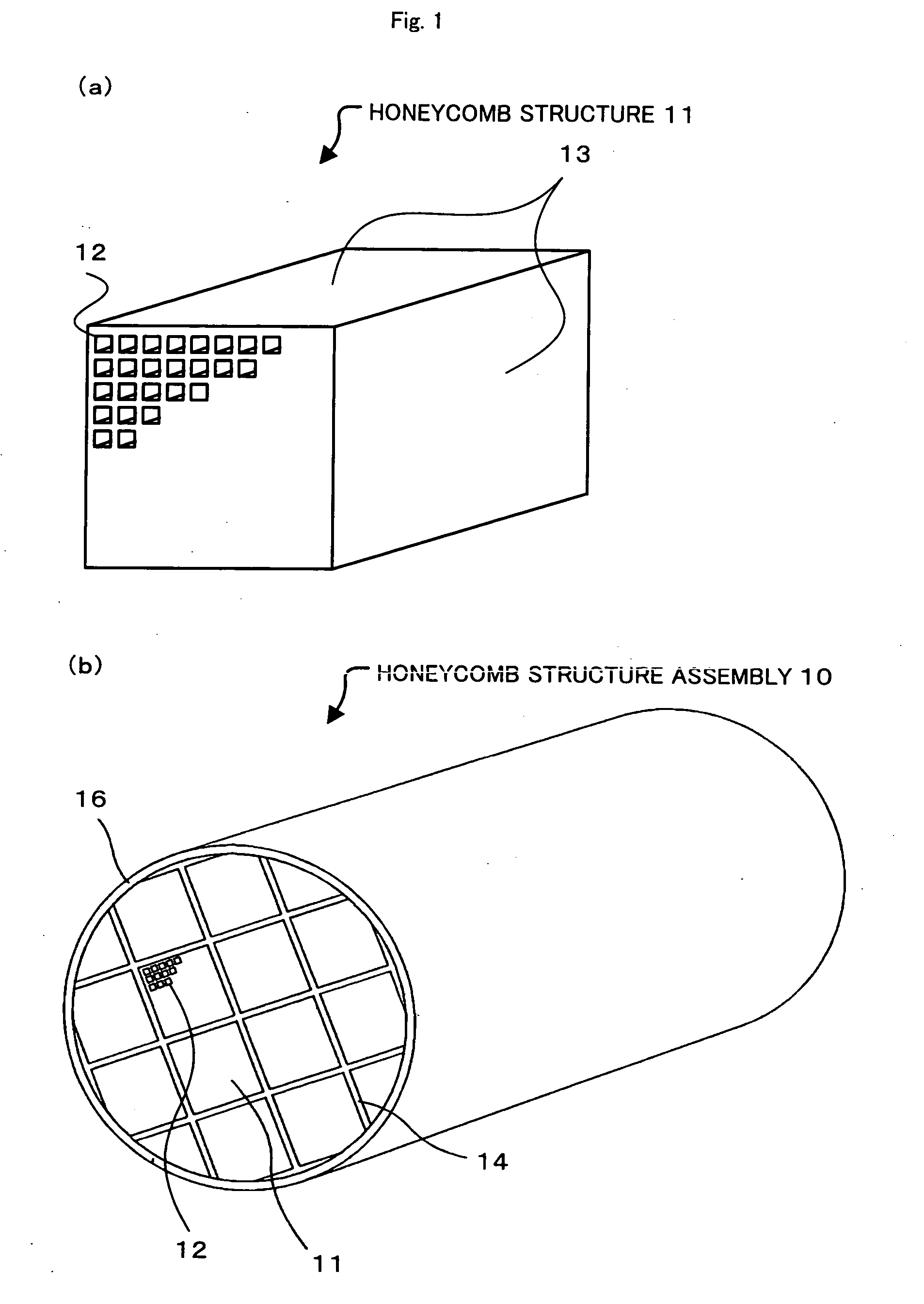
[0048] The process of Example 1 mixed 40% by weight of γ-alumina particles (average particle diameter: 2 μm), 10% by weight of silica alumina fibers (average fiber diameter: 10 μm, average fiber length: 100 μm), and 50% by weight of silica sol (solid content: 30% by weight) to give a mixture. The process added 6 parts by weight of methylcellulose as an organic binder and small amounts of a plasticizer and a lubricant with stirring to 100 parts by weight of the mixture and sufficiently kneaded the whole mixed composition. The mixed composition was extrusion molded by an extruder to a raw molded object. The raw molded object was sufficiently dried with a microwave dryer and a hot air dryer and was kept at 400° C. for 2 hours for degreasing. The degreased molded object was fired at 800° C. for 2 hours to give a square-pillar honeycomb structure (34.3 mm×34.3 mm×150 mm) having a cell density of 62 cells / cm2 (400 cpsi) and a wall thickness of 0.25 mm.

[0049] The honeycomb structure thus ...

example 2 to 12

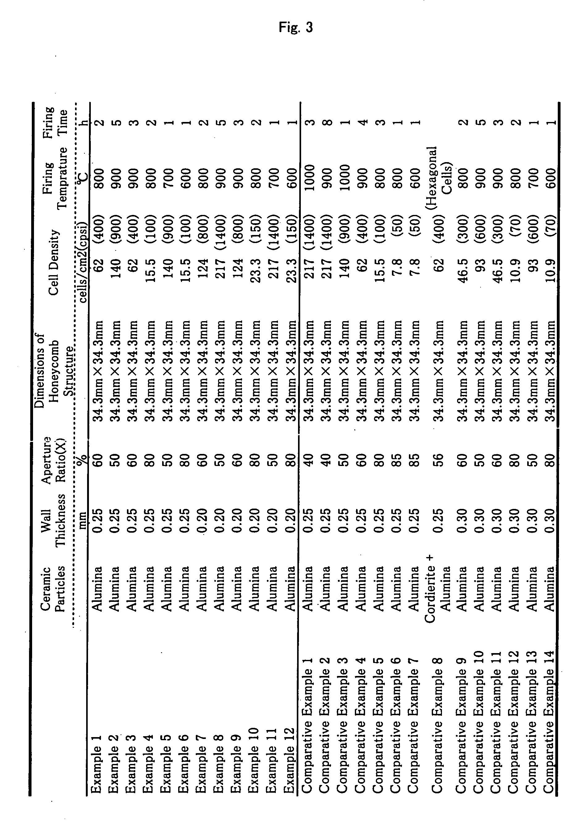
[0050] Honeycomb structures of Examples 2 to 12 having wall thicknesses, aperture ratios, and cell densities shown in the table of FIG. 3 were obtained from the same starting materials mixed at the same mixing ratio as those of Example 1 by the same procedure as Example 1 under respective preparation conditions shown in the table of FIG. 3. These honeycomb structures were treated by the same procedure as Example 1 to carry the catalyst component thereon. This gave honeycomb catalysts of Examples 2 to 12.


PUM

PropertyMeasurementUnit
Percent by massaaaaaaaaaa
Thicknessaaaaaaaaaa

Abstract

A honeycomb structure having multiple through holes includes at least ceramic particles and an inorganic binder. A wall thickness of each wall between adjoining through holes, on which a catalyst component is carried, is designed to be not greater than about 0.25 mm. The honeycomb structure satisfies a relation of Y≧250×X+22500 (50≦X≦80), where X denotes an aperture ratio (%) of a honeycombed face of the honeycomb structure perpendicular to the multiple through holes and Y denotes a specific surface area per unit volume (m2/L) of the honeycomb structure.

Description

CROSS REFERENCE TO RELATED APPLICATION [0001] This is a continuation of Application No. PCT / JP2005 / 001871, filed on Feb. 2, 2005, now abandoned.BACKGROUND ART [0002] 1. Technical Field [0003] The present invention relates to a honeycomb structure, a honeycomb structure assembly, and a honeycomb catalyst. [0004] This application claims benefit of priority to Japanese Patent Application No.2004-028186, filed on Feb. 4, 2004, the contents Of which are incorporated by reference herein. [0005] 2. Prior Art to be Disclosed [0006] A honeycomb catalyst including a honeycomb structure with a catalyst component carried thereon is used to convert the exhaust gas of vehicles. The honeycomb catalyst is conventionally manufactured by making a material of a high specific surface area, for example, active alumina, and a catalyst metal, for example, platinum, carried on the surface of an integral cordierite honeycomb structure of low thermal expansion characteristic. An alkaline earth metal, such as...

Claims


Application Information

Patent Timeline
IPC IPC(8): F01N3/10B01D53/94B01J21/12B01J23/42B01J32/00B01J35/04F01N3/28
CPCB01D53/9431B01J35/04F01N2330/48F01N2330/06F01N3/2828F01N3/28
Inventor OHNO, KAZUSHIGEKUNIEDA, MASAFUMIOGYU, KAZUTAKE
Owner IBIDEN CO LTD
Why Eureka
Try Eureka