Machining time calculating apparatus

a technology of calculating apparatus and machining process, which is applied in the direction of electric controllers, programme control, total factory control, etc., can solve the problems of inability to accurately calculate the axis moving time in the machining process, significant problems in production scheduling or order fulfillment, and the inability to use the obtained estimate for production scheduling without further processing, so as to achieve the effect of effectively producing machined products without waste and accurate calculation of the axis moving tim

Active Publication Date: 2005-10-13
OKUMA CORP
View PDF11 Cites 38 Cited by
  • Summary
  • Abstract
  • Description
  • Claims
  • Application Information

AI Technical Summary

Benefits of technology

[0023] With an apparatus according to a first aspect of the present invention, it is possible to accurately calculate the axis moving time even in a machining process which uses a numeric control apparatus having a function to optimally adjust the feeding velocity and acceleration / deceleration. Therefore, by establishing a production schedule using the axis moving time calculated by the machining time calculating apparatus of the present invention, it is possible to more effectively produce machined products without waste.
[0024] For example, in a mold machining process in which experience is of little benefit for improving the precision of estimation of the machining time because machining times vary between a few hours to a few tens of hours and the proportion of the axis moving time is very high, the present invention can provide a great advantage. In addition, because the NC machine tool need not be actually operated and the machining time can be quickly estimated, it is not necessary to use an expensive NC machine tool for estimating the machining time, making it possible to instead efficiently and effectively use the NC machine tool for its intended, profitable use of machining.
[0025] In an apparatus according to a further aspect of the present invention, an NC parameter such as an upper limit of the feeding velocity and the allowed acceleration of a machine which is used when a numeric control apparatus drives and controls an NC machine tool is stored for each numeric control apparatus and a desired NC parameter is selected. With this structure, it is possible to accurately calculate the axis moving time, even when the numeric control apparatus controls a plurality of NC machine tools having different properties and even when the different types of numeric control apparatuses are employed.
[0026] According to the apparatus of the third aspect of the present invention, various interpolation algorithms are stored corresponding to the numeric control apparatus and an interpolation algorithm for which the machining time calculation is desired is selected. With this structure, it is possible to accurately calculate the axis moving time even in a numeric control apparatus which uses a different interpolation algorithm.

Problems solved by technology

That is, it is not possible to accurately calculate the axis moving time in a machining process by a numeric control apparatus having the interpolation algorithm to automatically adjust the feeding velocity and acceleration / deceleration.
For example, in a machining operation, such as the machining of a mold in which the axis moving time occupies a large proportion of the time compared to the time when the auxiliary function is executed, a large difference between an estimated machining time and the actual machining time will result from an error in calculating the axis moving time, creating a significant problem in production scheduling or order fulfillment.
Thus, there had been a problem in that the obtained estimate cannot be used for production scheduling without further processing.
The axis moving time may significantly vary even when one factor is slightly changed, and, thus, it has been difficult to use the experience and to accurately correct the calculated machining time.
However, in this method, it is necessary to actually operate the NC machine tool using the target part program, and thus, in a machining process such as a mold machining which requires few hours to few tens of hours, this time is required for estimating the machining time.
Moreover, because the NC machine tool cannot be used during this period for other purposes, such as the actual machining and preparation of machining, this method is impractical.
In addition, this method requires that an actual machining time calculating unit be directly connected to the NC machine tool, and, therefore, this method is not suited for a system in which a required time for each production process is calculated and a production schedule is established based on the calculated time.

Method used


Image

  • Machining time calculating apparatus
  • Machining time calculating apparatus
  • Machining time calculating apparatus

Examples


Embodiment Construction

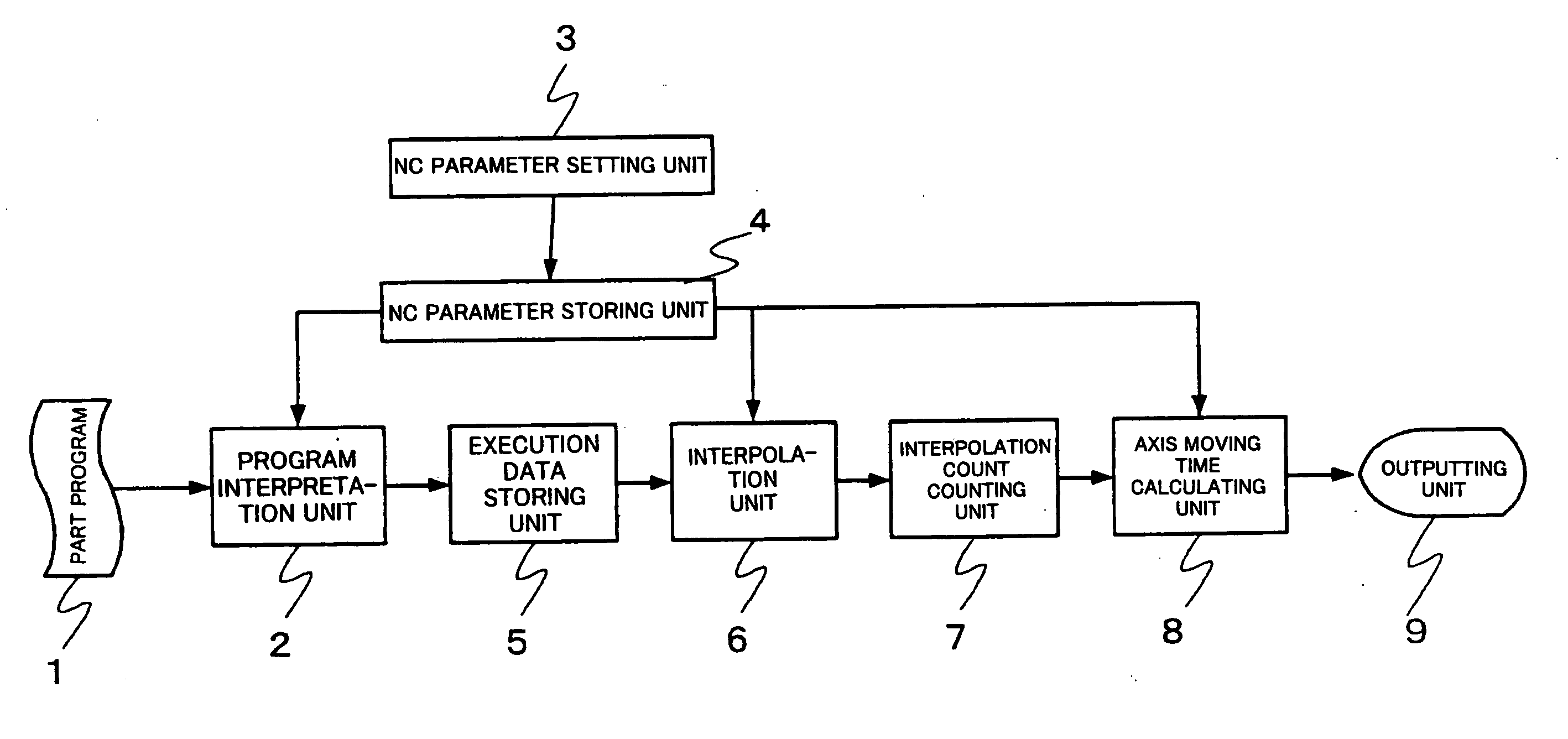
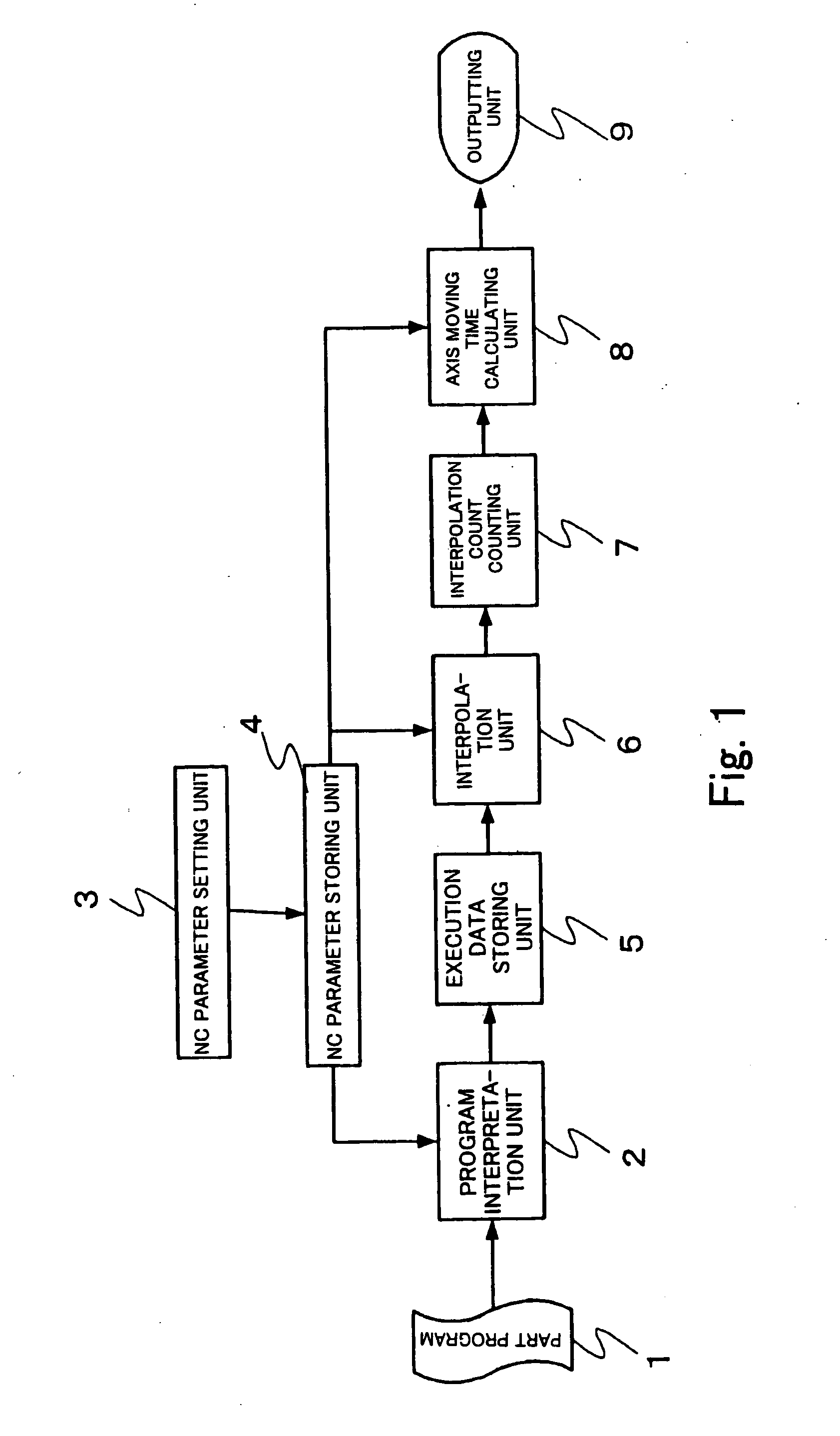
[0037] A first preferred embodiment will now be described referring to FIG. 1 and an example axis moving operation. A part program 1, an NC parameter setting unit 3, and an NC parameter storing unit 4 are identical to those described with respect to the numeric control apparatus of the related art and will not described again.

[0038] A program interpretation unit 2 reads the part program 1 which is a target for which the machining time is to be calculated, sequentially interprets the part program 1 for each block, generates machining data for each block, and stores the machining data in an execution data storing unit 5. In this process, the program interpretation unit 2 refers to an NC parameter such as a unit system of program instruction and tool radius stored in the NC parameter storing unit 4. The machining data for each block which is generated is data similar to the machining data for each block explained with respect to the numeric control apparatus of the related art.

[0039]...


PUM


Abstract

A structure having a parameter storing unit which stores a parameter to be used when a numeric control apparatus drives and controls the numeric control machine tool, a program interpretation unit which reads a part program to generate machining data for each block, an interpolation unit which interpolates a movement path instructed in an axis moving instruction referring to a parameter stored in the parameter storing unit and using an interpolation algorithm which is identical to a driving and controlling interpolation algorithm of the numeric control apparatus, an interpolation count counting unit which counts an interpolation count in the movement path, and an axis moving time calculating unit which multiplies an interpolation cycle when the numeric control apparatus drives and controls the numeric control machine tool and the counted interpolation count to calculate an axis moving time.

Description

BACKGROUND OF THE INVENTION [0001] 1. Field of the Invention [0002] The present invention relates to an apparatus for calculating the time required for machining in machining using an NC (Numeric Control) machine tool, and in particular to an apparatus for calculating an axis moving time when the numeric control apparatus itself has an algorithm for adjusting the feeding velocity or the like for achieving an optimum machining process. [0003] 2. Description of the Related Art [0004] When a production schedule or the like is made, a schedule is established based on the required time for each production process and in consideration of operation state of the production equipment and load of an operator so that the schedule is effective and waste in resources is minimized. The required time for each production process is estimated by collecting past performance and from experience. [0005] The required time for a machining step using the NC machine tool depends to a great extent on a part...

Claims


Application Information

Patent Timeline
Patent Type & Authority Applications(United States)
IPC IPC(8): G05B19/418G05B19/4103
CPCG05B19/4103G05B2219/34093G05B2219/34087G05B2219/34084Y02P90/02
Inventor HIOKI, KATSUYAYAMAGUCHI, TAKAHIRO
Owner OKUMA CORP
Why Eureka
Try Eureka