Structure of a twin disc type tool turret mechanism for CNC machines

a technology of twin disc type and tool turret, which is applied in the direction of tool holders, mechanical equipment, manufacturing tools, etc., can solve the problems that the precision of the turret cannot be reduced by cutting and dirt deposits, and achieve the effect of simple structure, reduced purchase and maintenance costs, and reduced precision of the turr

Inactive Publication Date: 2005-10-20
FACTORY AUTOMATION TECH CO LTD
View PDF10 Cites 3 Cited by
  • Summary
  • Abstract
  • Description
  • Claims
  • Application Information

AI Technical Summary

Benefits of technology

[0023] In the present tool turret mechanism, single servomotor or single stepper motor is used as the power source, and direction of transmission of power is controlled with the help of pistons and the transmission shaft; there is no need for hydraulic motors, complicated oil passages or control mechanisms for hydraulic motors therefore purchase and maintenance cost can be reduced. And, final gear ratio of power transmission to the internal turret is equal to that of power transmission to the external turret, and the present mechanism is suitable for use with high speed machining center. Cuttings and dirt won't be deposited in a small space between the internal and the external turrets because size of the small space between the turrets can't be changed. Therefore, precision of the turrets can't be reduced by cutting and dirt deposit. Cooling water guiding unit is away from the central part of the present turret mechanism, and not passed through the central shaft therefore the turret mechanism has simpler structure, and takes less cost to build. The water supply passages and the switching mechanism for the water supply passages are simplified in the structure therefore the distance between edges of the turrets can be shortened, and weight of the turrets reduces, and the shank of a tool used for boring a work piece doesn't have to be projected as long as before, allowing precision of boring to be increased, and allowing high speed machining.

Problems solved by technology

Therefore, precision of the turrets can't be reduced by cutting and dirt deposit.

Method used


Image

  • Structure of a twin disc type tool turret mechanism for CNC machines
  • Structure of a twin disc type tool turret mechanism for CNC machines
  • Structure of a twin disc type tool turret mechanism for CNC machines

Examples


Embodiment Construction

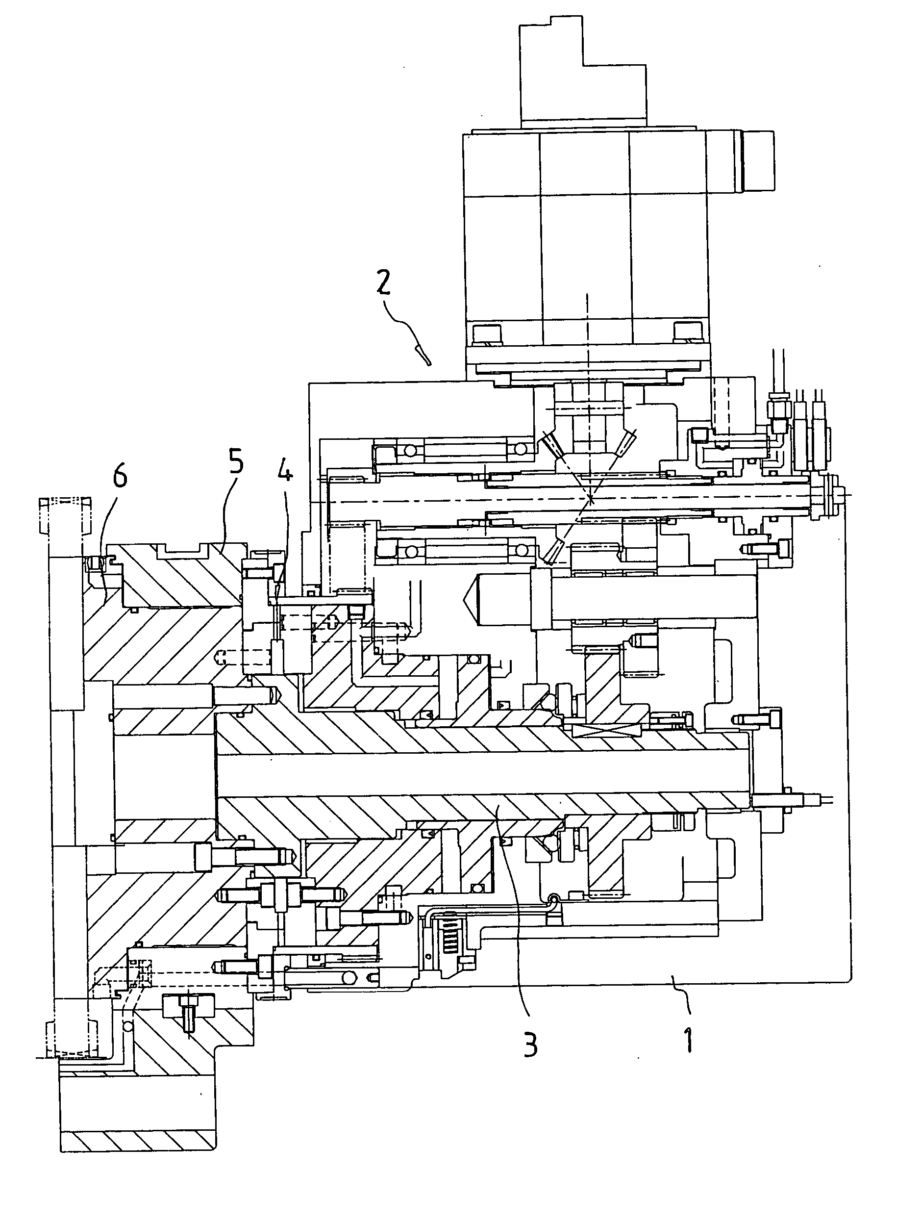
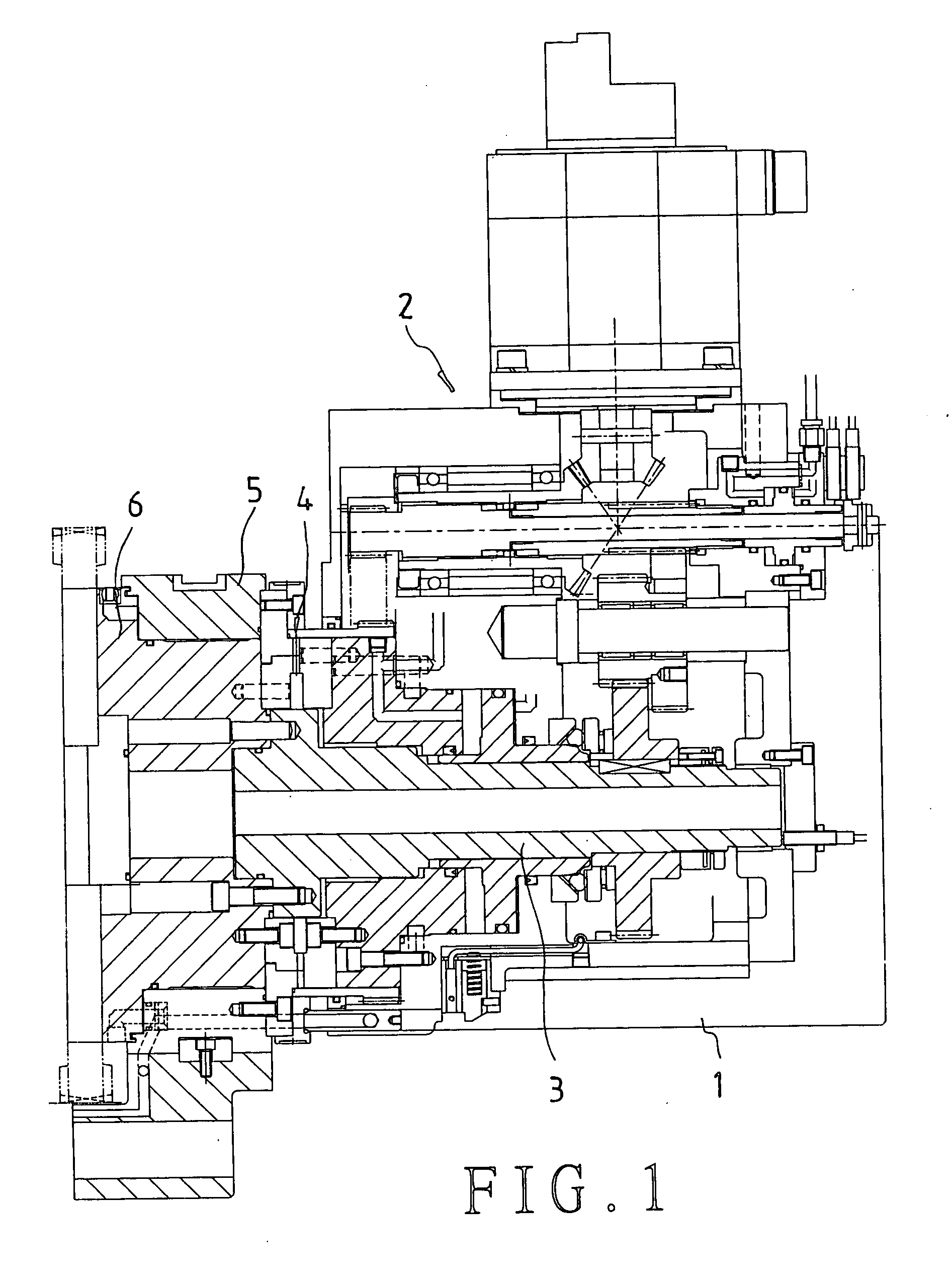
[0033] Referring to FIG. 1, a preferred embodiment of a twin disk type tool turret mechanism in the present invention includes a turret housing 1, a power switching mechanism 2, a central shaft 3, a clutch 4, an internal turret 5, and an external turret 6.

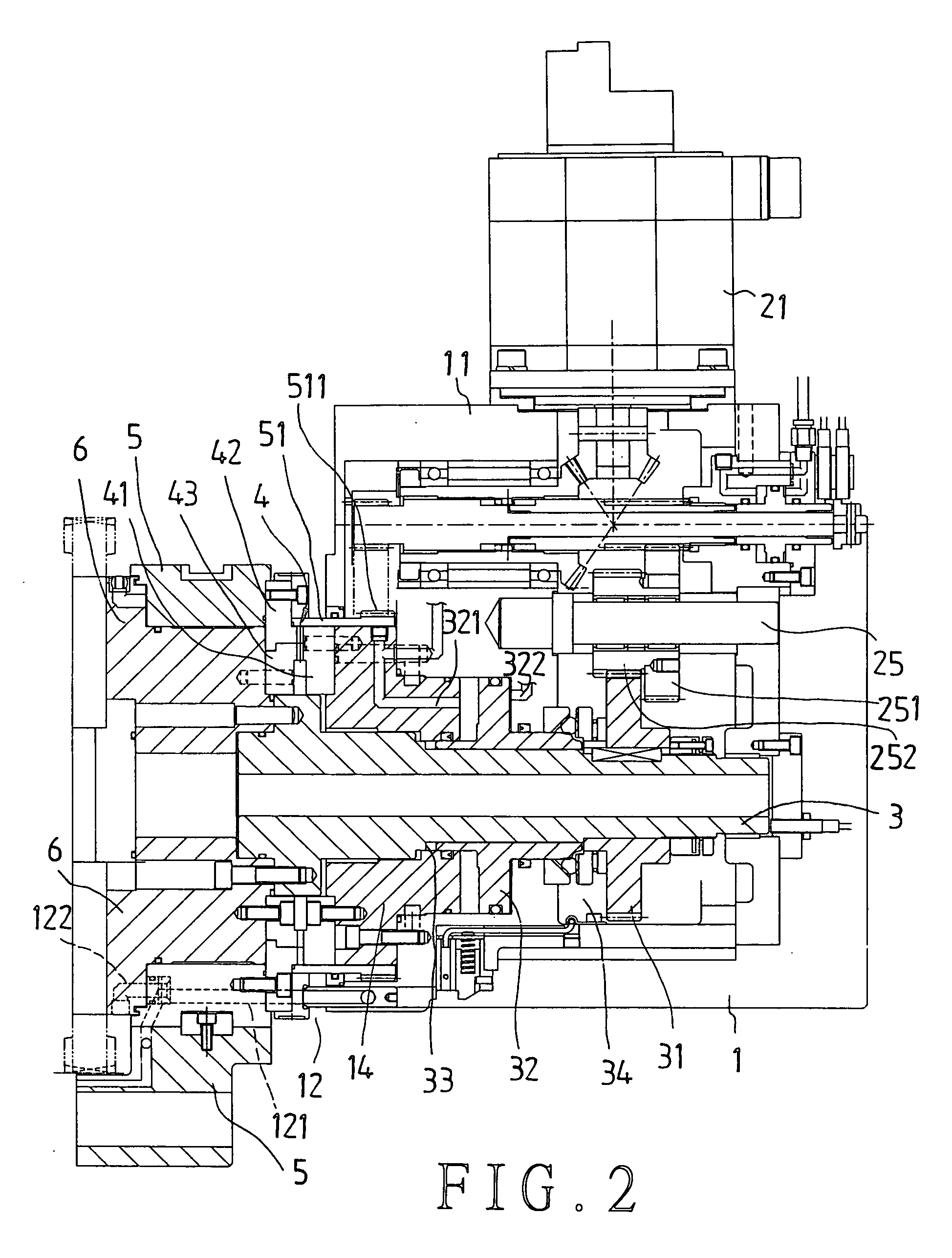
[0034] Referring to FIGS. 1 to 3, the turret housing 1 has a projecting seat 11, and is equipped with a water guiding unit 12, which has through holes 121, and 122, on the other side of the projecting seat 11; thus, cutting fluid can flow into the internal turret 5 as well as the external turret 6 through the holes 121, 122 of the water guiding unit 12. A power source 21 of the power switching mechanism 2 is secured to the projecting seat 11, which power source 21 can be a stepper motor or a servomotor.

[0035] The power source 21 of the power switching mechanism 2 has a bevel gear 211 connected thereto, which is engaged with a bevel gear 221 of a rotary sleeve 22. The rotary sleeve 22 has a central hole, and a transmission shaft 2...


PUM

PropertyMeasurementUnit
poweraaaaaaaaaa
axial movementaaaaaaaaaa
rotationaaaaaaaaaa

Abstract

A tool turret mechanism includes internal and external tool turrets, a toothed ring secured to the internal tool turret, a central shaft secured to the external turret, a power switch, and a clutch; the central shaft has a piston fitted thereto; the power switch is used for providing power to the internal and the external turrets through the toothed ring and the shaft respectively; the clutch includes a fixed clutch claw, external and internal ring clutch claws, which are respectively securely connected to inner edge of the internal turret, and inner edge of the external turret; the ring clutch claws will rotate, and engage each other; when the piston is actuated, and displaced, the external turret will be forced to change position, and both the turrets will be left and right displaced between a first position, in which they engage the clutch, and a second position, in which they disengage the clutch.

Description

BACKGROUND OF THE INVENTION [0001] 1. Field of the Invention [0002] The present invention relates to a twin disk type tool turret mechanism for a NC machine, more particularly one, which is equipped with single stepper motor or a servomotor, instead of conventional hydraulic mechanism, as the power source for internal and external tool turrets thereof such that the turret mechanism can be improved in respect of efficiency and reliability, and can be used with a precision control for increasing the efficiency in tool choosing action, and can be made simpler in the structure. [0003] 2. Brief Description of the Prior Art [0004] In U.S. Pat. No. 4,706,351, a twin disk type tool turret mechanism is taught, which includes: [0005] a turret housing; [0006] front turret and a rear turret means mounted in the housing, the two turrets being mounted so that they can be separately rotated for tool selection with said rear turret being axially fixed and said front turret being axially moveable; [...

Claims


Application Information

Patent Timeline
Patent Type & Authority Applications(United States)
IPC IPC(8): B23B29/00B23B29/32
CPCB23B29/323B23B2250/12B23B2260/044Y10T29/5155Y10T29/5157Y10T74/1494Y10T29/5154Y10T82/2587Y10T29/5167Y10T74/1476Y10T29/5153
Inventor LU, YUNG-HSIANG
Owner FACTORY AUTOMATION TECH CO LTD
Why Eureka
Try Eureka