Semiconductor device

a technology of semiconductors and components, applied in the direction of sustainable manufacturing/processing, final product manufacturing, foundation engineering, etc., can solve the problems of low-cycle fatigue in the connection parts, ensuring connection reliability, and reducing so as to improve the reliability of the connection parts, the effect of increasing the capacity and increasing the functionality

Inactive Publication Date: 2005-10-20
ELPIDA MEMORY INC
View PDF3 Cites 5 Cited by
  • Summary
  • Abstract
  • Description
  • Claims
  • Application Information

AI Technical Summary

Benefits of technology

[0024] According to the present invention, a semiconductor device can be obtained having improved reliability of the connection parts between the semiconductor package and the package substrate against heat load and that enables greater capacity, higher functionality, and better space-saving capability.

Problems solved by technology

As a result, when heat load is applied to the device due to the heat generation of the semiconductor device during operation or changes in the ambient temperature, the difference in the amount of thermal deformation between the electronic components and the package substrate produces thermal stress in the connection parts of the electronic components and the package substrate.
When this thermal stress is great, there is a danger of low-cycle fatigue in the connection parts and consequent disconnection.
In particular, in a semiconductor device having high-density packaging, the dimensional tolerances of the connection parts are small, and ensuring connection reliability therefore becomes a key issue.
In a semiconductor device in which electronic components are connected to the package substrate by a plurality of solder bumps, the difference in the amount of thermal deformation between the electronic components and the package substrate produces a high level of plastic strain on lines in the direction of the center of the electronic component in the solder bumps that are at positions remote from the center of the electronic component, with the resulting problem of a drastic reduction of the life of the connection.

Method used


Image

  • Semiconductor device
  • Semiconductor device
  • Semiconductor device

Examples


second working example

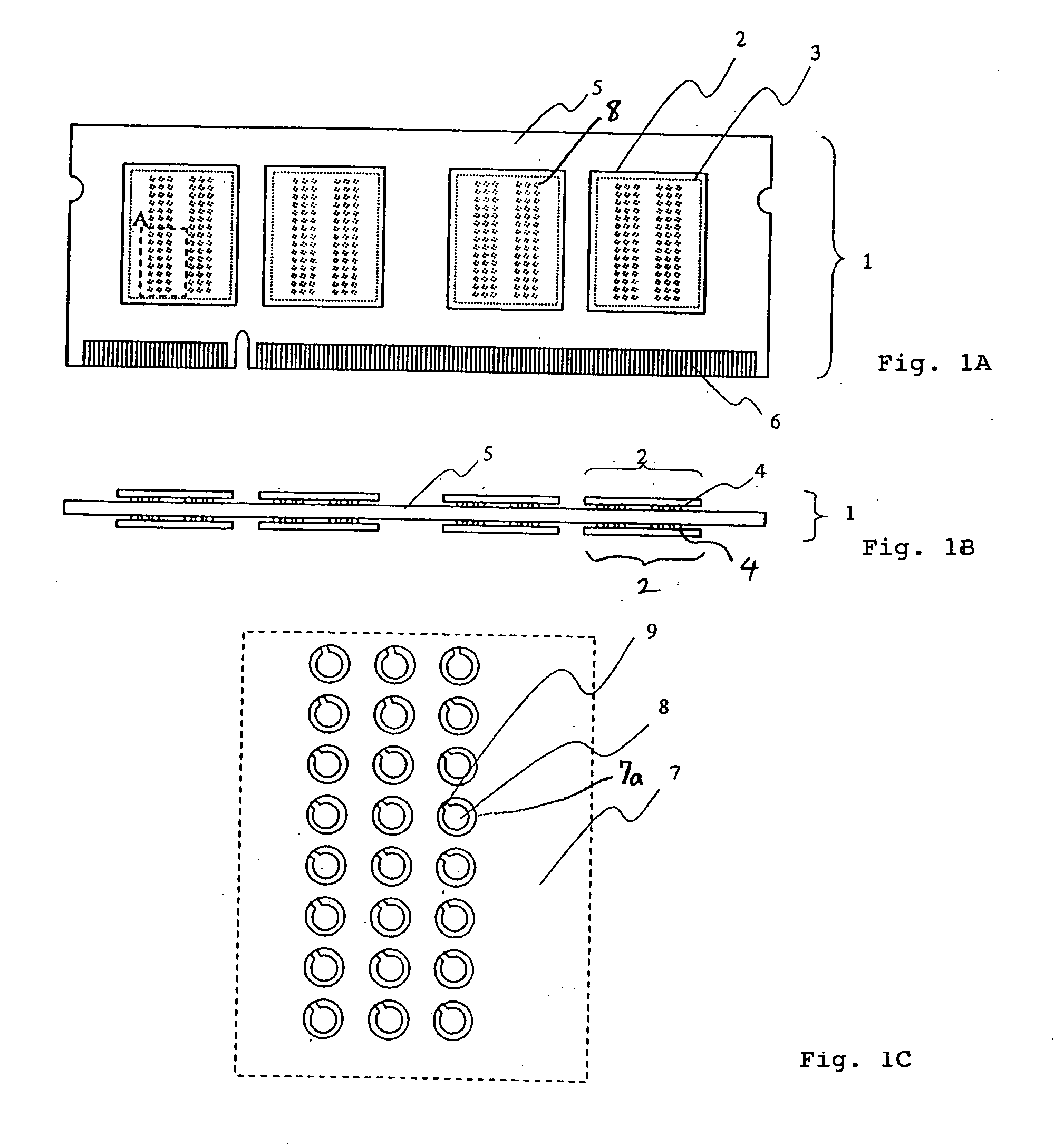
[0101]FIG. 9A is an overall plan view of the semiconductor device of the second working example of the present invention, FIG. 9B is a side view of the semiconductor device, and FIG. 9C is an enlarged view of portion A in which the semiconductor packages of FIG. 9A have been omitted.

[0102] The second working example differs from the first working example in that, while interconnections 9 are provided at all lands 8 in the first working example, in the second working example, lands 111 that are electrically unconnected and do not use interconnections 9 are provided in a portion of lands 8. These lands 111 that do not use interconnections 9 do not have an electrical function, but the provision of these lands 111 can improve the reliability of other connection parts in which electrical conduction has been established. In particular, the provision of lands 111 in the corners or peripheral portions of semiconductor package 2 can improve the reliability of the connection parts that are a...

third working example

[0103]FIG. 10A is an overall plan view of the semiconductor device of the third working example of the present invention, FIG. 10B is a side view of the semiconductor device, and FIG. 10C is an enlarged view of portion A in which the semiconductor packages of FIG. 10A have been omitted.

[0104] The third working example differs from the first working example in that, while all lands 8 are arranged in a grid in the first working example, some locations are not provided with lands 8 in the third working example. When the number of connection pins that is electrically required is less than the number of grid points, not providing lands 8 in a portion of the grid can facilitate the routing of interconnections on the package substrate and can increase the freedom of the mounting position of the package. In this case, there is a concern that the range of plastic strain that occurs at solder bumps 36 will increase when compared with a case in which lands 8 are provided at all points in a gr...

fourth working example

[0105]FIG. 11A is an overall plan view of the semiconductor device of the fourth working example of the present invention, FIG. 11B is a side view of the semiconductor device, and FIG. 11C is an enlarged view of portion A in which the semiconductor packages of FIG. 11A have been omitted.

[0106] The point of difference between the first working example and the fourth working example is that, while interconnections 9 that are led out from all lands 8 are provided in the direction in which the range of plastic strain of the solder is small in the first working example, in the fourth working example, a portion of interconnections 9 are provided in a direction in which the range of plastic strain of the solder is great. Lands 8 in which interconnections 9 are provided in a direction in which the range of plastic strain of the solder is great are power supply pins 131. Arranging interconnections in a direction in which the range of plastic strain of the solder is great raises the concern ...


PUM


Abstract

A semiconductor device is provided with a semiconductor package 2 and a package substrate 5 having lands 8 that electrically connect by way of solder bumps 4 to the semiconductor package 2. A plurality of columns, in each of which a multiplicity of lands 8 are arranged, are formed on the package substrate 5. At least one of the lands 8 that make up columns that are located closest to each of the main sides that make up the outer edges of the semiconductor package has an interconnection 9 that extends from the land 8 along the surface of the package substrate. The interconnection 9 is formed such that the part that contacts the land 8 is located closer to a line that passes through the center of the land 8 and that is orthogonal to a line that connects the center of the land 8 with the center of the semiconductor package 2 than to the line that connects the center of the land 8 with the center of the semiconductor package 2.

Description

BACKGROUND OF THE INVENTION [0001] 1. Field of the Invention [0002] The present invention relates to a semiconductor device having lands for forming electrical connections with semiconductor packages by way of solder bumps. [0003] 2. Description of the Related Art [0004] Semiconductor memories are used in a wide variety of information devices such as large-scale computers, personal computers, and portable apparatuses, and the capacity and speed demanded of semiconductor memories increases with each year. Because greater capacity and higher speed are accompanied by an increase in the chip dimensions of the semiconductor memory, semiconductor elements must be packaged with a high density in the limited space of a package substrate. As one technology for realizing high-capacity memory in a limited package area, semiconductor devices are being developed in which CSP (Chip Size Packages), which are semiconductor packages having substantially the same dimensions as the area of semiconduct...

Claims


Application Information

Patent Timeline
Patent Type & Authority Applications(United States)
IPC IPC(8): H05K1/02H01L21/56H01L21/60H01L23/12H01L23/31H01L23/48H01L25/065H01L25/10H01L25/18H05K1/11H05K3/34
CPCH01L21/563H01L2225/06565H01L25/0657H01L2224/48091H01L2224/73203H01L2224/73265H01L2924/15311H05K1/111H05K2201/09281H05K2201/094H05K2201/10734H01L23/3114H01L2225/06517H01L24/48H01L2924/01087H01L25/105H01L2225/0651H01L2924/00014H01L2924/181H01L2224/32225Y02P70/50H01L2924/00012H01L2224/45099H01L2224/45015H01L2924/207B66C23/203E02D27/42
Inventor WATANABE, YUJIKATAGIRI, MITSUAKITANIE, HISASHINAKAMURA, ATSUSHISATO, TOMOHIKO
Owner ELPIDA MEMORY INC
Why Eureka
Try Eureka