Process for producing biodegradable molded item and molding dies therefor
- Summary
- Abstract
- Description
- Claims
- Application Information
AI Technical Summary
Benefits of technology
Problems solved by technology
Method used
Image

Examples
embodiment 1
[0119] An embodiment of the present invention is described below in accordance with FIGS. 1 to 18. By the way, the present invention is not limited to this embodiment.
[0120] First, a biodegradable molded article manufactured by a method of the present invention is described.
[0121] The biodegradable molded article manufacture by a method of the present invention contains a biodegradable expanded molded article of a specific shape obtained by molding a molding material through steam expansion, and a coating film attached to a surface thereof, said coating film being mainly made of a biodegradable plastic and having at least hydrophobicity.
[0122] In the above biodegradable molded article, it is preferable that a ratio of volume of air phase included in the biodegradable expanded molded article is more than 30 volume % of total volume of the biodegradable molded article. This increases a surface area of the biodegradable expanded molded article and helps to bring in microorganisms bi...
embodiment 2
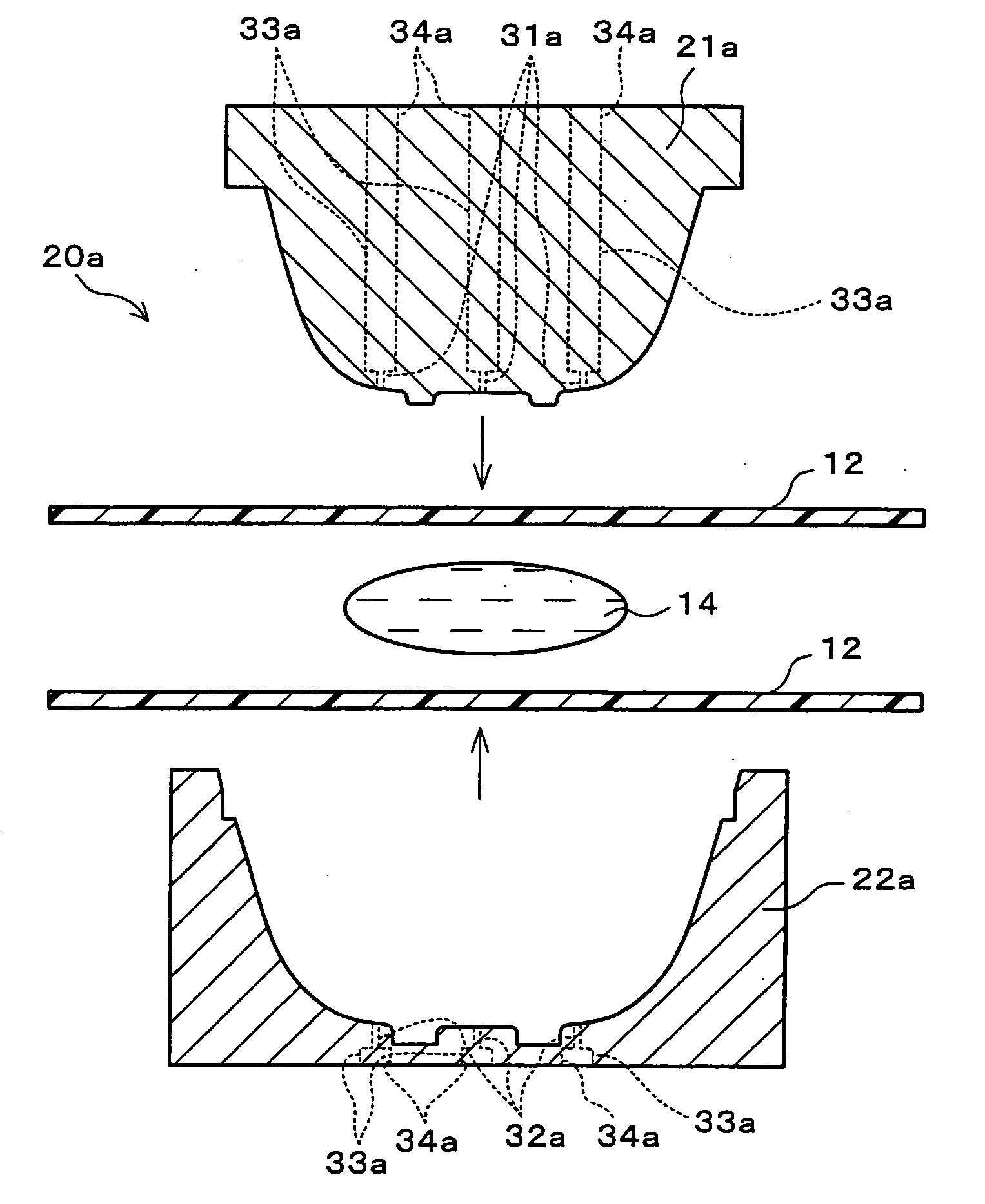
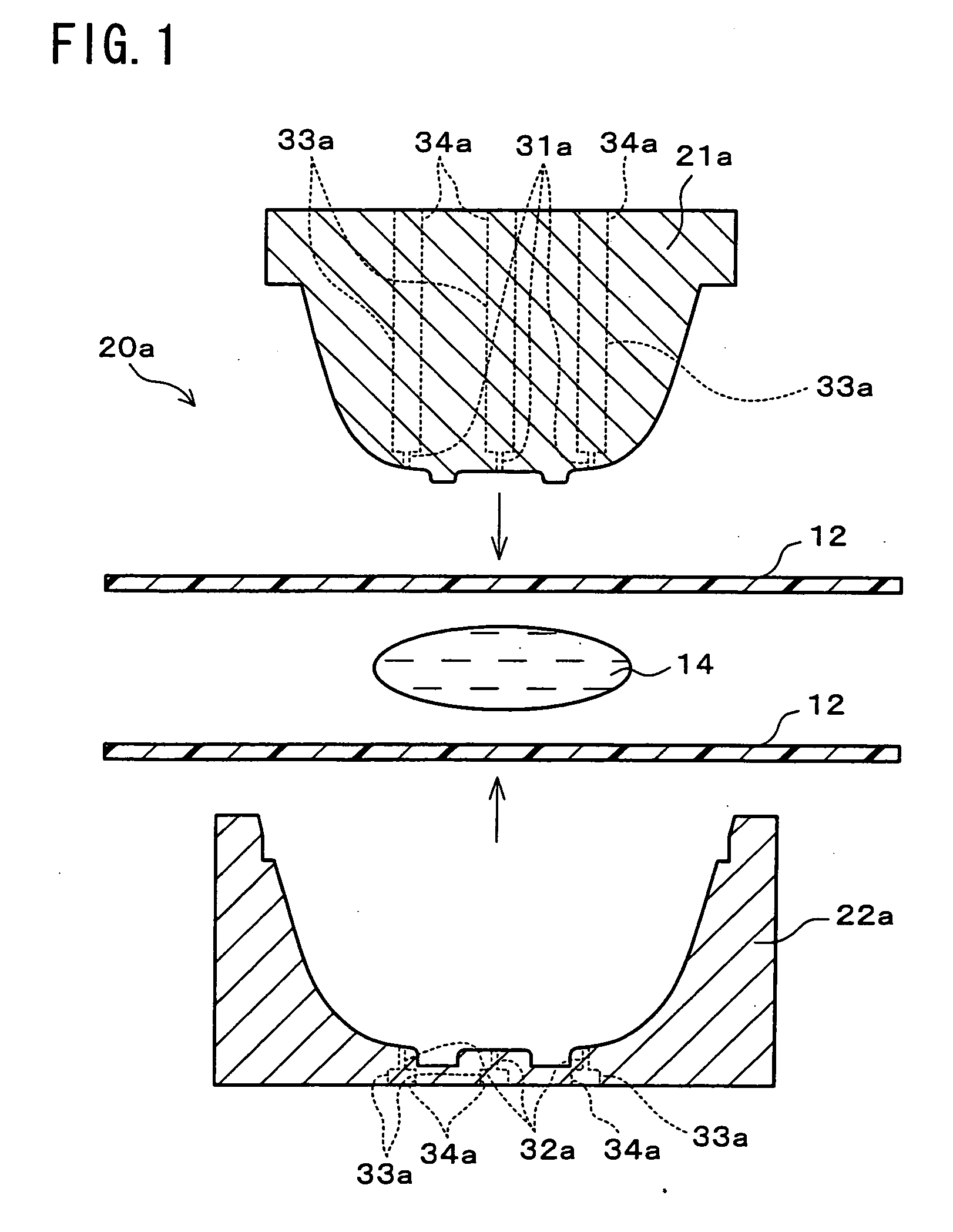
[0358] An embodiment of the present invention is described below based on FIG. 20 to FIG. 24. The present invention is not limited to this embodiment. For convenience of explanation, the members having the same function as each member shown in the above embodiment 1 have the same code with no explanation.
[0359] First, a biodegradable molded article manufactured by a method of this embodiment has a structure that a coating film is formed directly on a surface of an expanded molded article, as the biodegradable molded article manufactured by the method of Embodiment 1.
[0360] The method of this embodiment is a method to manufacture a biodegradable molded article of a deep drawing shape, or a method suitable to manufacture a biodegradable molded article of a deep drawing shape.
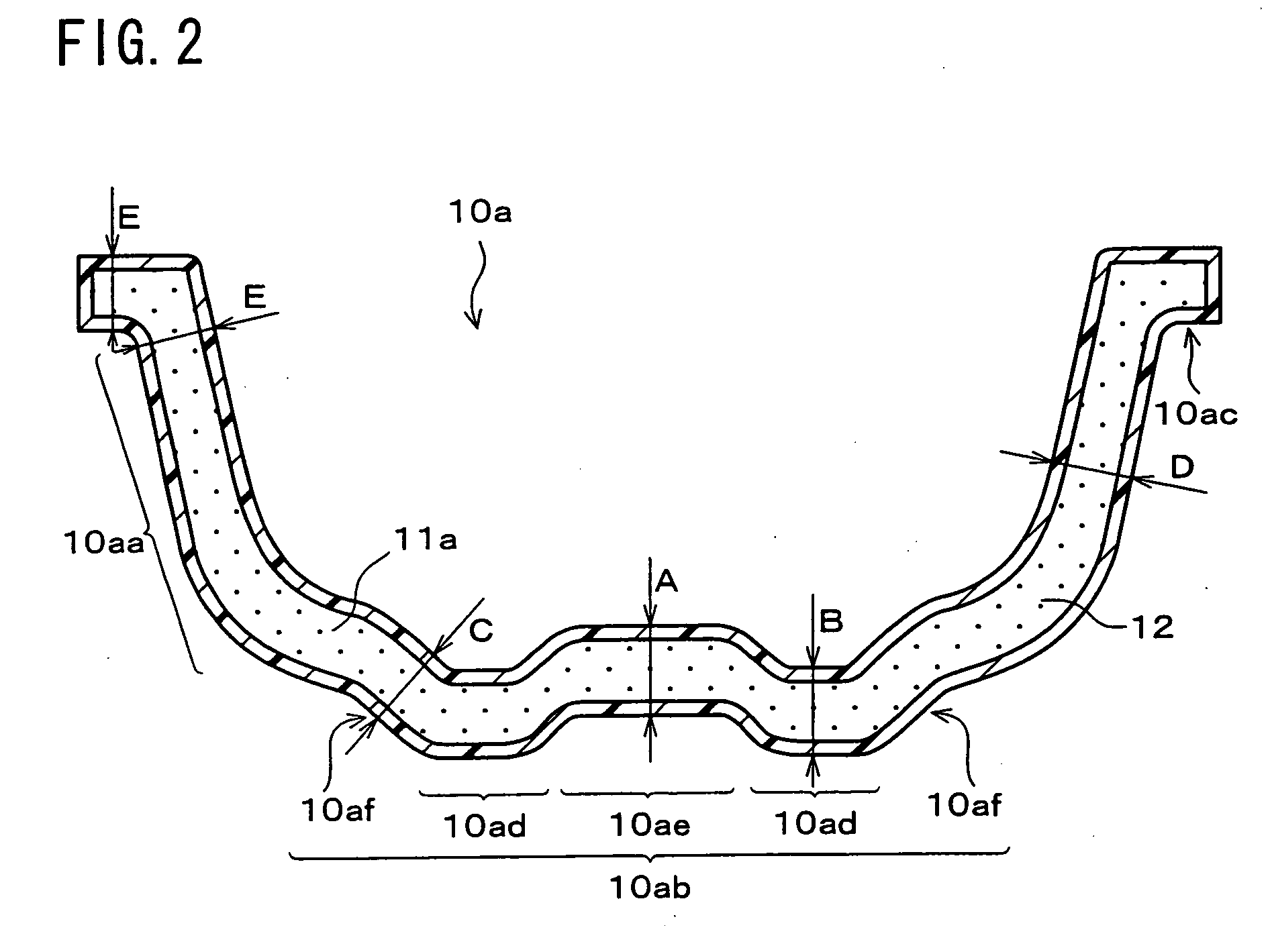
[0361] The biodegradable molded article of a deep drawing shape is, for example, the bowl-shaped container 10a shown in FIG. 2 explained in Embodiment 1, an almost similar bowl-shaped container such as the bowl...
example 1
[0412] For all of the combinations (16 combinations in total) of 8 molding materials (1) to (8) shown in Table 1 as the molding material 14 and two coating films F3 and F5 shown in Table 2 as the coating film 12, a round plate-shaped container 10b was manufactured by the method of Embodiment 1 explained with FIGS. 6(a) and 6(b).
[0413] Using the metal mold 20b having the exhaust holes 31b and 32b shown in FIGS. 6(a) and 6(b) and with the cavity 25b in uniform thickness of 2.5 mm (corresponding to thickness of the round plate-shaped container 10b), the molding material 14 is placed between a pair of coating films 12 in the metal mold 20b. Then, the metal mold is clamped by fitting the convex mold part 21b in the concave mold part 22b, the main body 11b is obtained by heating and molding the molding material 14 and the coating film 12 in the metal mold 20b and steam-expanding the molding material 14, and at the same time, the coating film 12 is softened and pressure-bonded to the surf...
PUM
| Property | Measurement | Unit |
|---|---|---|
| Temperature | aaaaa | aaaaa |
| Temperature | aaaaa | aaaaa |
| Temperature | aaaaa | aaaaa |
Abstract
Description
Claims
Application Information
 - Generate Ideas
- Intellectual Property
- Life Sciences
- Materials
- Tech Scout
- Unparalleled Data Quality
- Higher Quality Content
- 60% Fewer Hallucinations
Browse by: Latest US Patents, China's latest patents, Technical Efficacy Thesaurus, Application Domain, Technology Topic, Popular Technical Reports.
© 2025 PatSnap. All rights reserved.Legal|Privacy policy|Modern Slavery Act Transparency Statement|Sitemap|About US| Contact US: help@patsnap.com