In band signal detection and presentation for IP phone

a technology of in-band signal detection and ip phone, applied in digital transmission, data switching by path configuration, electrical equipment, etc., can solve the problems of frame jitter, inconvenient transmission delay, inconvenient detection, etc., and achieve the effect of reducing jitter

Active Publication Date: 2005-10-20
INNOMEDIA PTE
View PDF8 Cites 55 Cited by
  • Summary
  • Abstract
  • Description
  • Claims
  • Application Information

AI Technical Summary

Benefits of technology

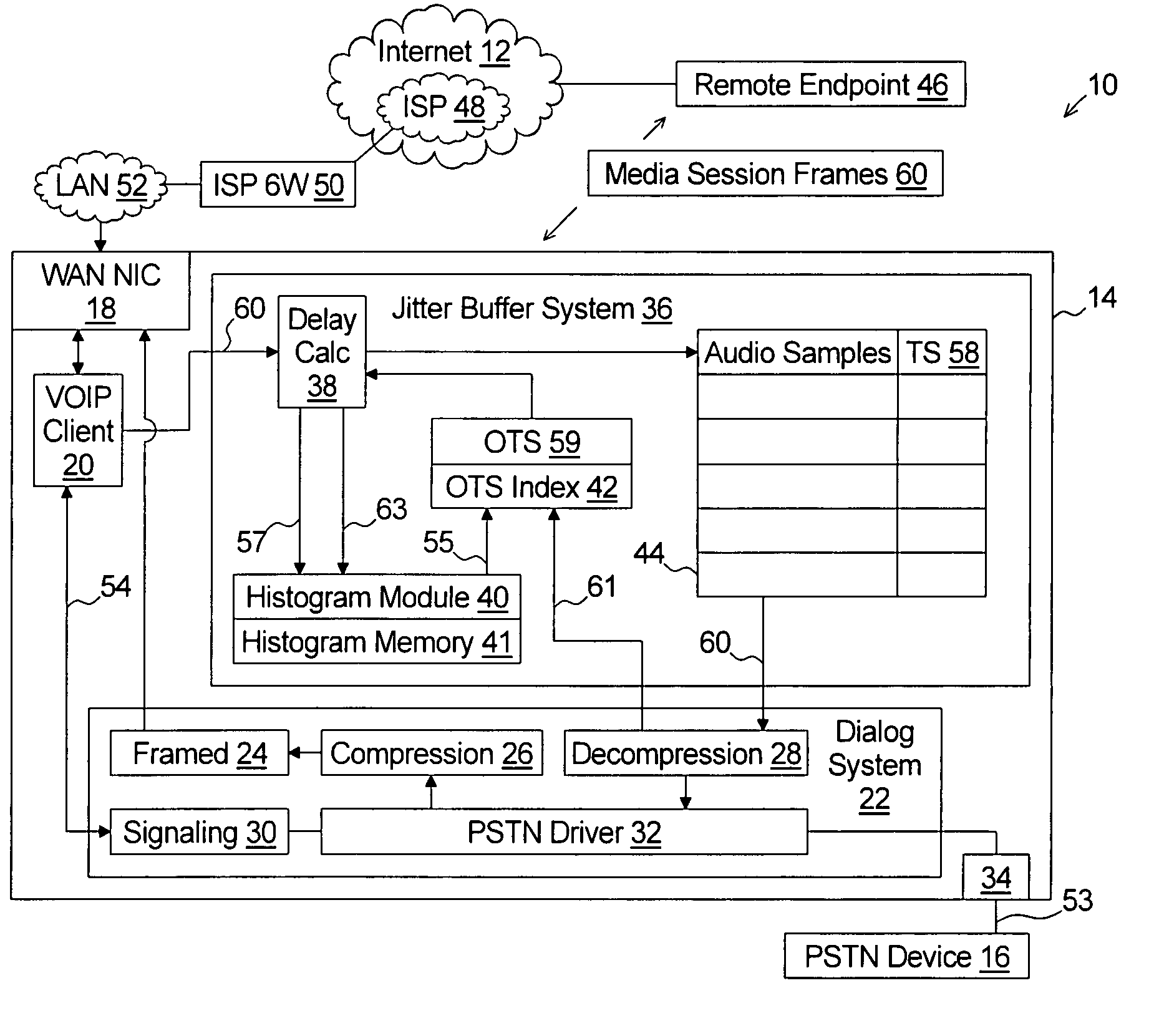
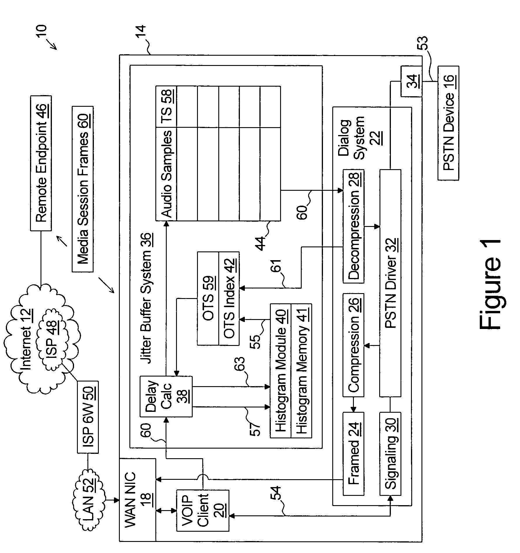
[0011] A first aspect of the present invention is an improved adaptive jitter buffer system for reducing jitter in a packet audio reception device such as a Voice over Internet Protocol (VoIP) telephone or terminal adapter.

Problems solved by technology

Due to speech or other audio data being continuous in nature, an imperceptible and constant transmission delay is required to accurately reproduce the speech or other audio data at a receiving system.
A problem with use of VoIP for maintaining a telephone call between two stations is that the transmission latency is not constant.
Further, frames may arrive out of sequence or may not even arrive at all if the frame is lost in a buffer overflow at a router along the Internet.
This jitter and frame loss can cause gaps and clipping in the reproduced audio.
While a large jitter buffer with significant delay reduces the probability of the buffer becoming empty or overflowing, the significant delay itself degrades the quality of the telephone call.
Known adaptive jitter buffer systems are slow to react to changes in frame jitter.

Method used


Image

  • In band signal detection and presentation for IP phone
  • In band signal detection and presentation for IP phone
  • In band signal detection and presentation for IP phone

Examples


Embodiment Construction

[0029] The present invention will now be described in detail with reference to the drawings. In the drawings, each element with a reference number is similar to other elements with the same reference number independent of any letter designation following the reference number. In the text, a reference number with a specific letter designation following the reference number refers to the specific element with the number and letter designation and a reference number without a specific letter designation refers to all elements with the same reference number independent of any letter designation following the reference number in the drawings.

[0030] It should also be appreciated that many of the elements discussed in this specification may be implemented in a hardware circuit(s), a processor executing software code, or a combination of a hardware circuit(s) and a processor or control block of an integrated circuit executing machine readable code. As such, the term circuit, module, server...


PUM


Abstract

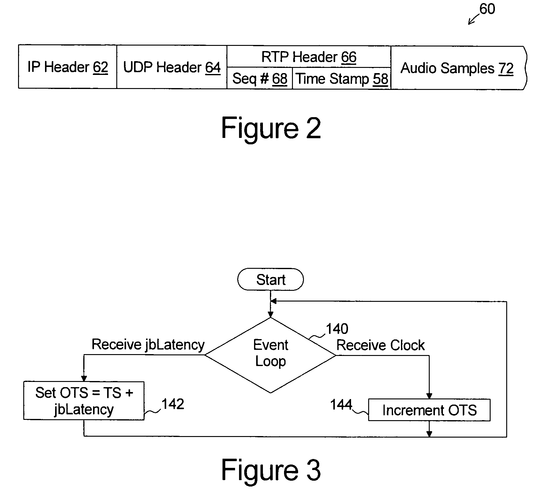
A jitter buffer system for reducing jitter in a packet audio reception device comprises an output time stamp index, a delay calculation module, and a histogram module. The output time stamp index determines an initial output time stamp value upon receipt of a jitter buffer latency value and increments the output time stamp upon release of each of the frames by a jitter buffer. The delay calculation module calculates a delay value for each of the sequence of received frames. The delay value is equal to the time difference between the output time stamp value and a transmission time stamp assigned to the frame by the transmitting system. The histogram module is coupled to each of the output time stamp index and the delay calculation module, the histogram module periodically calculates a target delay value which, based on a buffered history of values representing the delay value of each of a fixed quantity of the most recently received frames from the sequence of receive frames, would have resulted in a predetermined portion of the fixed quantity of frames being dropped, and adjusting the jitter buffer latency value to a value equal to the target value.

Description

TECHNICAL FIELD [0001] The present invention relates to packet voice communications, and more particularly to systems and methods which correct for variable latency in receipt of data packets containing compressed audio data. BACKGROUND OF THE INVENTION [0002] For many years voice telephone service was implemented over a circuit switched network commonly known as the public switched telephone network (PSTN) and controlled by a local telephone service provider. In such systems, the analog electrical signals representing the conversation are transmitted between the two telephone handsets on a dedicated twisted-pair-copper-wire circuit. More specifically, each of the two endpoint telephones is coupled to a local switching station by a dedicated pair of copper wires known as a subscriber loop. The two switching stations are connected by a trunk line network comprising multiple copper wire pairs. When a telephone call is placed, the circuit is completed by dynamically coupling each subsc...

Claims


Application Information

Patent Timeline
Patent Type & Authority Applications(United States)
IPC IPC(8): H04J3/06H04L29/06
CPCH04J3/0632H04L65/80H04L29/06027H04L65/1101
Inventor KAVALER, ROBERT A.
Owner INNOMEDIA PTE
Why Eureka
Try Eureka