Solid high polymer type cell assembly

a polymer and cell technology, applied in the field of solid polymer cell assembly, can solve the problems of large pressure loss, and achieve the effect of high porosity, easy installation at various positions, and suitability

Inactive Publication Date: 2005-10-20
HONDA MOTOR CO LTD
View PDF1 Cites 65 Cited by
  • Summary
  • Abstract
  • Description
  • Claims
  • Application Information

AI Technical Summary

Benefits of technology

[0009] Since the flow rate of the reactant gas required for reaction in the downstream unit cell (the unit cell on the downstream side) is taken into account, and the additional reactant gas is supplied to the upstream unit cell (the unit cell on the upstream side), the flow rate of the reactant gas supplied into the cell assembly is high. Thus, water condensation in the reactant gas flow passage is prevented, and the humidity is uniform in each of the unit cells. The current density distribution is uniform in each of the unit cells, and thus, concentration overpotential is reduced. Further, simply by increasing the flow rate of the reactant gas supplied into the cell assembly, water produced in each of the unit cells can be discharged efficiently. Water can be discharged from the cell assembly smoothly.
[0021] A connection passage member is provided between the juxtaposed unit cells. The connection passage member has a reactant gas connection passage and a coolant connection passage for serially supplying the reactant gas and the coolant. Thus, the cell assembly is compact as a whole, and the compact cell assembly can be installed at various positions easily and suitably.

Problems solved by technology

The pressure loss is large.

Method used


Image

  • Solid high polymer type cell assembly
  • Solid high polymer type cell assembly
  • Solid high polymer type cell assembly

Examples


first embodiment

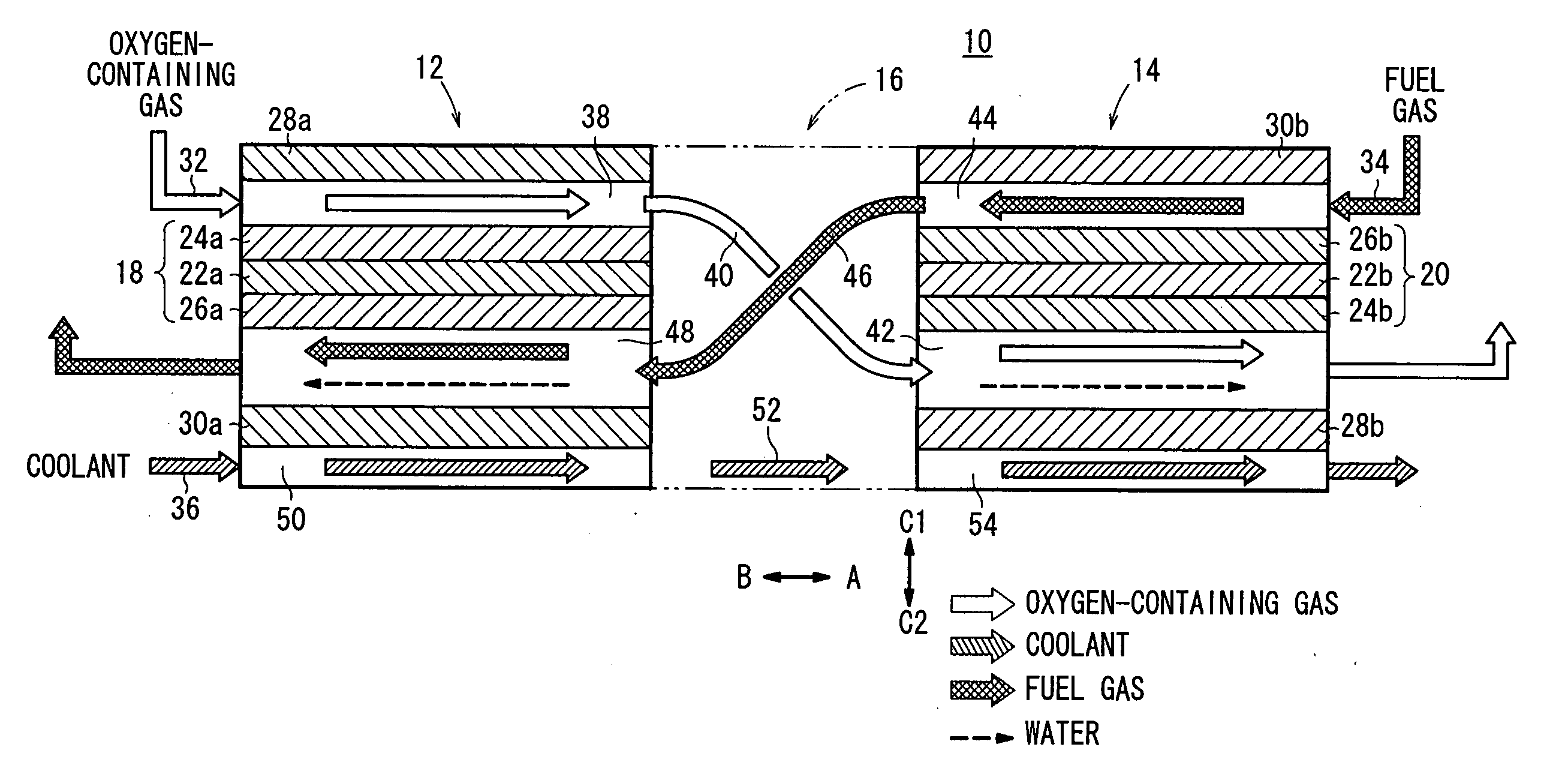
[0027]FIG. 1 is a view schematically showing main components of a solid polymer cell assembly 10 according to the present invention.

[0028] The cell assembly 10 includes a plurality of unit cells, e.g., a first unit cell 12 and a second unit cell 14 which are juxtaposed such that electrode surfaces of the first and second unit cells 12, 14 are aligned in parallel with each other. A connection passage member 16 is provided between the first and second unit cells 12, 14. The first unit cell 12 is provided on the upstream side in a flow direction of an oxygen-containing gas (reactant gas) indicated by an arrow A, and the second unit cell 14 is provided on the downstream side in the flow direction of the oxygen-containing gas.

[0029] The first unit cell 12 includes a first assembly 18, and the second unit cell 14 includes a second assembly 20. Each of the first assembly 18 and the second assembly 20 comprises a cathode 24a, 24b, an anode 26a, 26b, and a solid polymer electrolyte membrane...

second embodiment

[0068] As described above, in the second embodiment, a plurality of the first and second unit cells 12, 14 are stacked together to form the first and second fuel cell stacks 82, 84, respectively for achieving the high output easily. Further, in the structure in which the oxygen-containing gas can be supplied externally to the connection passage member 16, it is possible to effectively reduce the flow rate of the oxygen-containing gas supplied to the first fuel cell stack 82.

INDUSTRIAL APPLICABILITY

[0069] According to the present invention, the flow rate of the reactant gas supplied to the unit cell on the upstream side is high since the flow rate of the reactant gas supplied to the unit cell on the downstream side is taken into account. Thus, it is possible to prevent the water condensation in the reactant gas flow passage, and the humidity is uniform in each of the unit cells. Accordingly, the current density distribution is uniform in each of the unit cells, and the concentration...


PUM

PropertyMeasurementUnit
temperatureaaaaaaaaaa
structureaaaaaaaaaa
hydrophobicaaaaaaaaaa

Abstract

A cell assembly (10) includes a first unit cell (12) and a second unit cell (14). The first unit cell (12) and the second unit cell (14) are juxtaposed such that electrode surfaces of the first unit cell (12) and electrode surfaces of the second unit cell (14) are aligned in parallel with each other. An oxygen-containing gas flow passage (32) includes a first oxygen-containing gas passage (38) in the first unit cell (12), an oxygen-containing gas connection passage (40) in a connection passage member (16), and a second oxygen-containing gas passage (42) in the second unit cell (14). The first oxygen-containing gas passage (38), the oxygen-containing gas connection passage (40), and the second oxygen-containing gas passage (42) are connected serially from the first unit cell (12) to the second unit cell (14).

Description

TECHNICAL FIELD [0001] The present invention relates to a solid polymer cell assembly including a plurality of unit cells connected together. Each of the unit cells has an assembly including an anode, a cathode, and a solid polymer electrolyte membrane interposed between the anode and the cathode. The unit cells are juxtaposed such that electrode surfaces of the unit cells are aligned in parallel with each other. BACKGROUND ART [0002] Generally, a polymer electrolyte fuel cell (PEFC) employs an electrolyte membrane. The electrolyte membrane is a polymer ion exchange membrane (proton ion exchange membrane). The electrolyte membrane is interposed between an anode and a cathode to form an assembly (electrolyte electrode assembly). Each of the anode and the cathode includes base material chiefly containing carbon, and an electrode catalyst layer of noble metal deposited on the base material. The electrolyte electrode assembly is sandwiched between separators (bipolar plates) to form a u...

Claims


Application Information

Patent Timeline
Patent Type & Authority Applications(United States)
IPC IPC(8): H01M8/00H01M8/10H01M8/02H01M8/04H01M8/24
CPCH01M8/04089H01M8/04291Y02E60/50H01M8/249H01M8/241H01M8/2484H01M8/2418
Inventor WARIISHI, YOSHINORIENJOJI, NAOYUKIASANO, YOICHISHINKAI, HIROSHI
Owner HONDA MOTOR CO LTD
Why Eureka
Try Eureka