Ion beam device and ion beam processing method, and holder member

Active Publication Date: 2005-10-27
HITACHI HIGH TECH SCI CORP
View PDF5 Cites 116 Cited by
  • Summary
  • Abstract
  • Description
  • Claims
  • Application Information

AI Technical Summary

Benefits of technology

[0012] Furthermore, the holder member provided to the ion beam apparatus according to the invention preferably has a base part which is rotatably supported about a first axis in parallel with a horizontal direction, and a holding part which is rotatably disposed about a second axis orthogonal to the first axis at a tip end side of the base part and holds the sample. The holder member is rotatably disposed about the first axis, and thus the arrangement of the removing beam source with respect to the holder member and the flexibility in the irradiating direction of the gaseous ion beam can be secured. Moreover, the holder member has the holding part which is rotatably disposed about the second axis, and thus the irradiating directions of the focused ion beam and the gaseous ion beam can be varied with respect to the sample held by the holding part.

Problems solved by technology

However, when the traditional ion beam apparatus is used to perform ion beam fabrication for forming a micro-cross-section in a sample, gallium used for an ion source of the focused ion beam is injected into the cross section of the sample to alter the sample amorphously, and gallium forms a damage layer which is a so-called fracture layer with the damaged cross section.
Since the sample having this fracture layer formed on the observation cross section adversely affects relatively high-powered TEM observation by the fracture layer, there is a disadvantage that a normal crystal lattice image cannot be obtained, causing a problem in highly accurate observation up to the atomic level of the cross section.

Method used


Image

  • Ion beam device and ion beam processing method, and holder member
  • Ion beam device and ion beam processing method, and holder member
  • Ion beam device and ion beam processing method, and holder member

Examples


Embodiment Construction

[0032] Hereinafter, specific embodiments according to the invention will be described with reference to the drawings.

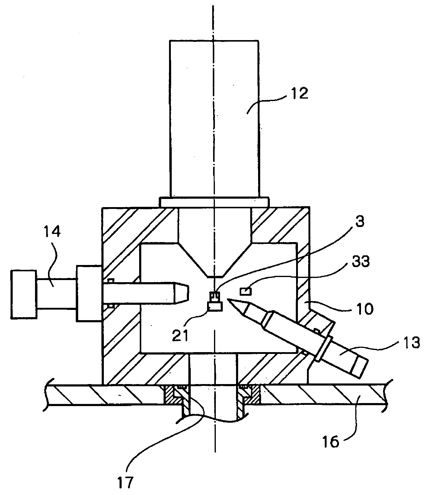
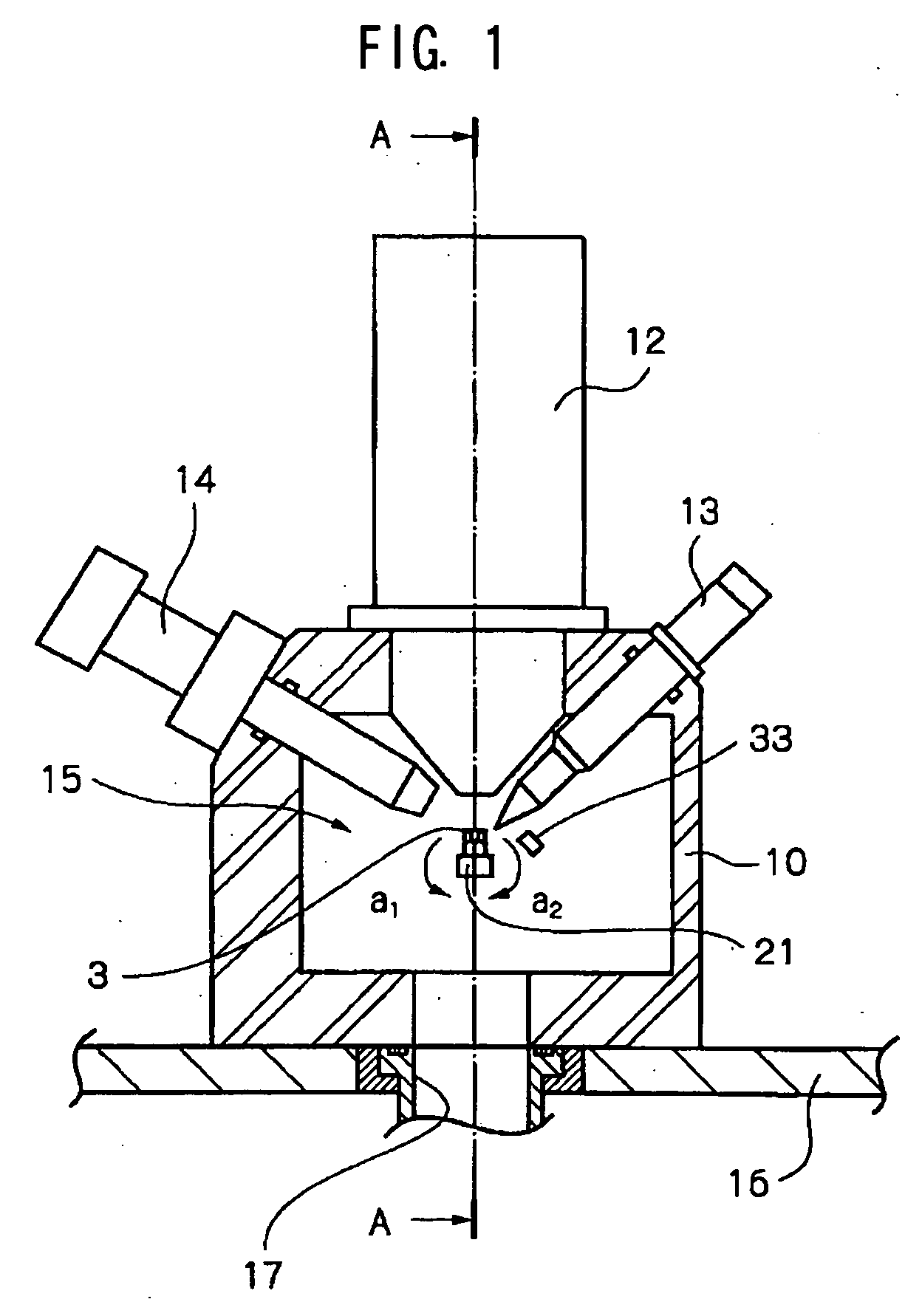
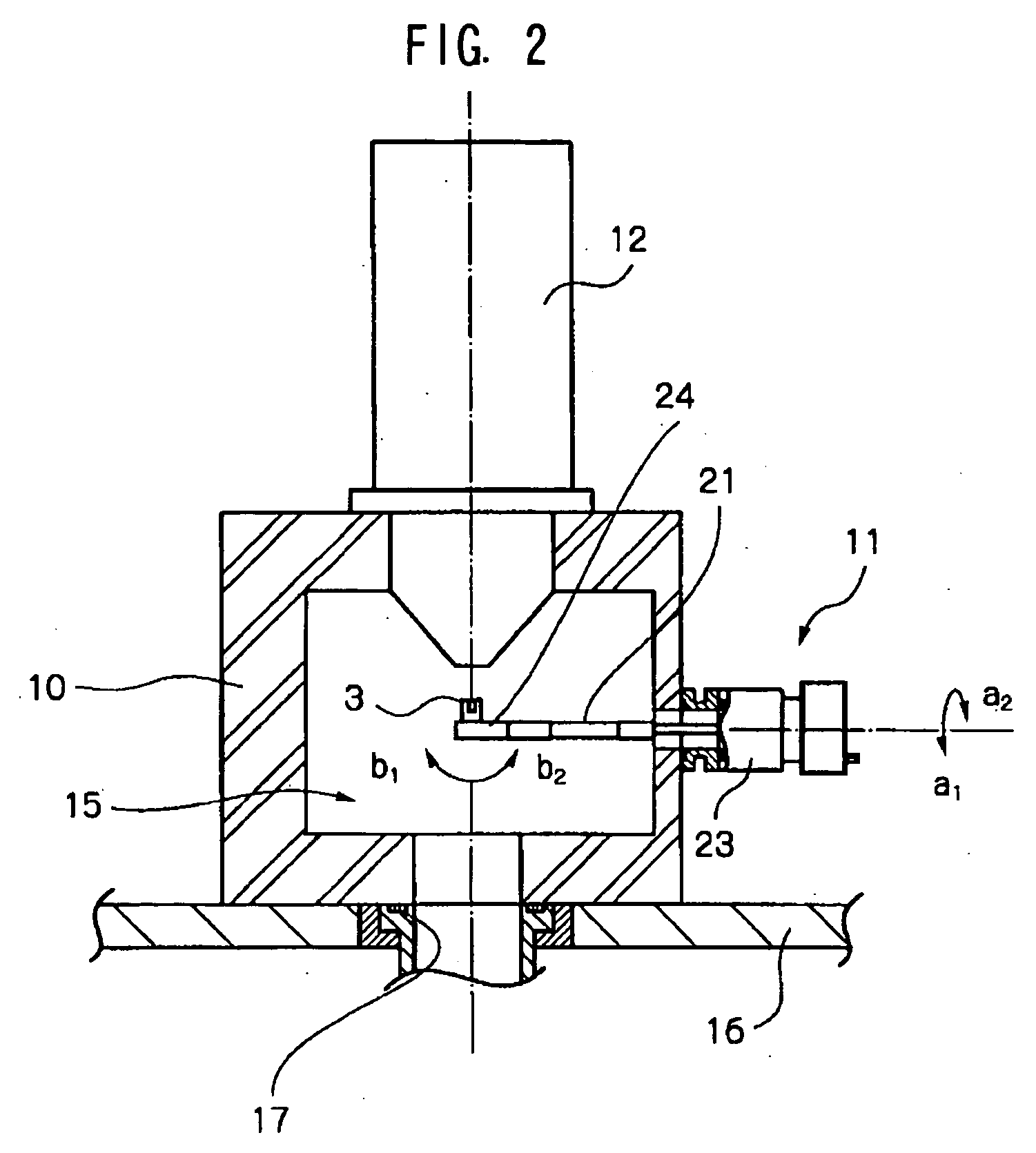
[0033] As shown in FIGS. 1 and 2, an ion beam apparatus 1 of this embodiment is a so-called side entry ion beam apparatus, having a vacuum container 10 which processes a sample 3 therein, a holder part 11 which holds the sample 3, a processing beam part 12 which irradiates a focused ion beam from a gallium ion source onto the sample 3 and processes an observation cross section, a removing beam part 13 which irradiates an inert ion beam onto the cross section processed in the sample 3 and removes a fracture layer on the cross section, and an observing beam part 14 which irradiates an electron beam onto the cross section of the sample 3 and observes the cross section.

[0034] First, the sample 3 to be processed by the ion beam apparatus 1 is cut out of a wafer in a given flat plate, and then the both ends thereof cut in the width direction to form it in a block shape as...


PUM


Abstract

An apparatus has a holder member (21) which holds a sample (3), and a removing beam source (13) which irradiates an inert ion beam onto a cross section (4) of the sample (3) held by a holder member (21) and removes a fracture layer on the cross section (4). Then, the removing beam source (13) is disposed on the holding end side of the sample (3) with respect to the normal L of the cross section (4) so that the irradiating direction of the inert ion beam is tilted at the tilt angle θ to the normal L with respect to the cross section (4).

Description

TECHNICAL FIELD [0001] The present invention relates to an ion beam apparatus, an ion beam processing method and a holder member for processing a cross section for observation in a sample that is used to observe a micro-structure of a semiconductor and the like, for example. BACKGROUND ART [0002] Traditionally, for example, an ion beam apparatus is widely used for the purpose of preparing a TEM sample that is used to observe defects generated in wafer fabrication processes of semiconductor memory and the like by a TEM (Transmission Electron Microscope) and the like. In this type of ion beam apparatus, ion beam fabrication by the focused ion beam (FIB: Focused Ion Beam) allows processing a micro-cross section for observation in a particular portion of a TEM sample, and allows preparing the TEM sample for a relatively short time. [0003] However, when the traditional ion beam apparatus is used to perform ion beam fabrication for forming a micro-cross-section in a sample, gallium used f...

Claims


Application Information

Patent Timeline
IPC IPC(8): G01N1/28G01N1/32G01N1/34G21K5/08H01J37/20H01J37/30H01J37/305H01L21/302
CPCG01N1/32H01J2237/31749H01J2237/31745H01J37/3056
Inventor KODAMA, TOSHIOHASUDA, MASAKATSUFUJII, TOSHIAKIIWASAKI, KOUJISUGIYAMA, YASUHIKOTAKAGI, YASUYUKI
Owner HITACHI HIGH TECH SCI CORP
Why Eureka
Try Eureka