GPU rendering to system memory

a technology of system memory and gpu, applied in the field of computer graphics, can solve the problems of limiting affecting the performance of unified memory architecture system, and requiring extra space for separate graphics processing subsystem memory, so as to prevent data bus deadlock and high degree of two-dimensional locality of rendered image data

Inactive Publication Date: 2005-10-27
NVIDIA CORP
View PDF8 Cites 88 Cited by
  • Summary
  • Abstract
  • Description
  • Claims
  • Application Information

AI Technical Summary

Benefits of technology

[0009] An embodiment of the invention enables a graphics processing subsystem to use system memory as its graphics memory for rendering and scanout of images. To prevent deadlock of the data bus, the graphics processing subsystem may use an alternate virtual channel of the data bus to access additional data from system memory needed to complete a write operation of a first data. In communicating with the system memory, a data packet including extended byte enable information allows the graphics processing subsystem to write large quantities of data with arbitrary byte masking to system memory. To leverage the high degree of two-dimensional locality of rendered image data, the graphics processing subsystem arranges image data in a tiled format in system memory. A tile translation unit converts image data virtual addresses to corresponding system memory addresses. The graphics processing subsystem reads image data from system memory and converts it into a display signal.

Problems solved by technology

However, having separate memory for the graphics processing subsystem increases costs significantly, not only because of the expense of extra memory, which can be hundreds of megabytes or more, but also due to the costs of supporting components such as power regulators, filters, and cooling devices and the added complexity of circuit boards.
Moreover, the extra space required for separate graphics processing subsystem memory can present difficulties, especially with notebook computers or mobile devices.
Traditionally, the data bus connecting the graphics processing subsystem with system memory limits the performance of unified memory architecture systems.
Improved data bus standards, such as the PCI-Express data bus standard, increase the bandwidth available for accessing memory; however, achieving optimal rendering performance with an unified memory architecture still requires careful attention to memory bandwidth and latency.
Moreover, the PCI-Express data bus standard introduces its own problems, including system deadlock and high overhead for selective memory accesses.
Because of this, performing scanout from a rendered image stored in system memory is difficult.

Method used


Image

  • GPU rendering to system memory
  • GPU rendering to system memory
  • GPU rendering to system memory

Examples


Embodiment Construction

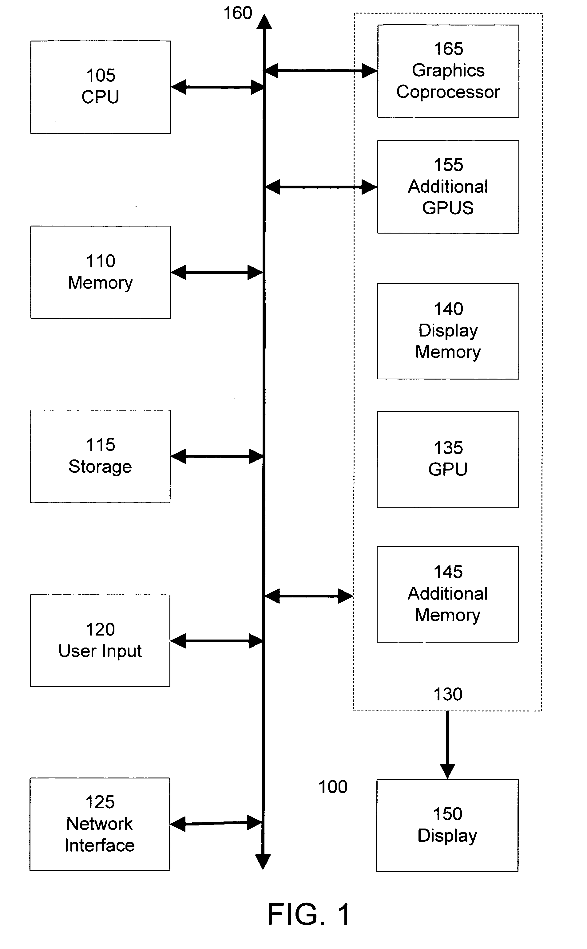
[0024]FIG. 1 is a block diagram of a computer system 100, such as a personal computer, video game console, personal digital assistant, or other digital device, suitable for practicing an embodiment of the invention. Computer system 100 includes a central processing unit (CPU) 105 for running software applications and optionally an operating system. In an embodiment, CPU 105 is actually several separate central processing units operating in parallel. Memory 110 stores applications and data for use by the CPU 105. Storage 115 provides non-volatile storage for applications and data and may include fixed disk drives, removable disk drives, flash memory devices, and CD-ROM, DVD-ROM, or other optical storage devices. User input devices 120 communicate user inputs from one or more users to the computer system 100 and may include keyboards, mice, joysticks, touch screens, and / or microphones. Network interface 125 allows computer system 100 to communicate with other computer systems via an e...


PUM


Abstract

A graphics processing subsystem uses system memory as its graphics memory for rendering and scanout of images. To prevent deadlock of the data bus, the graphics processing subsystem may use an alternate virtual channel of the data bus to access additional data from system memory needed to complete a write operation of a first data. In communicating with the system memory, a data packet including extended byte enable information allows the graphics processing subsystem to write large quantities of data with arbitrary byte masking to system memory. To leverage the high degree of two-dimensional locality of rendered image data, the graphics processing subsystem arranges image data in a tiled format in system memory. A tile translation unit converts image data virtual addresses to corresponding system memory addresses. The graphics processing subsystem reads image data from system memory and converts it into a display signal.

Description

CROSS-REFERENCES TO RELATED APPLICATIONS [0001] This application is related to U.S. Pat. No. 6,275,243, entitled “Method and apparatus for accelerating the transfer of graphical images” and issued Aug. 14, 2001, and the disclosure of this patent is incorporated by reference herein for all purposes.BACKGROUND OF THE INVENTION [0002] The present invention relates to the field of computer graphics. Many computer graphic images are created by mathematically modeling the interaction of light with a three dimensional scene from a given viewpoint. This process, called rendering, generates a two-dimensional image of the scene from the given viewpoint, and is analogous to taking a photograph of a real-world scene. [0003] As the demand for computer graphics, and in particular for real-time computer graphics, has increased, computer systems with graphics processing subsystems adapted to accelerate e the rendering process have become widespread. In these computer systems, the rendering process ...

Claims


Application Information

Patent Timeline
Patent Type & Authority Applications(United States)
IPC IPC(8): G06F12/02G06F12/08G06F13/28G09G5/39G09G5/393G09G5/395
CPCG06F12/0207G06F12/0875G09G2360/125G09G5/395G09G2360/122G09G5/393
Inventor RUBINSTEIN, ORENREED, DAVID G.ALBEN, JONAH M.
Owner NVIDIA CORP
Why Eureka
Try Eureka