Smaller electrolytic capacitors for implantable defibrillators

a technology of electrolytic capacitors and implantable defibrillators, which is applied in the field of electrolytic capacitors, can solve the problems of increasing the life of the capacitor, and achieve the effects of reducing the thickness of the capacitor lid, reducing the diameter of the normally empty mandrel region, and reducing the spa

Inactive Publication Date: 2005-10-27
CARDIAC PACEMAKERS INC
View PDF99 Cites 6 Cited by
  • Summary
  • Abstract
  • Description
  • Claims
  • Application Information

AI Technical Summary

Benefits of technology

[0011] One improvement contributing to this size reduction is the use of one or more separators having a thickness less than the standard one-thousandth of an inch used in conventional electrolytic capacitors. The exemplary embodiment uses combinations of paper separators with thicknesses of 0.000787, 0.0005, and 0.00025 inches. For conventional cylindrically wound active elements, reducing separator thickness reduces the space necessary to contain the separators. In turn, this allows one to reduce the diameter and volume of the active element and thus the total volume of the capacitor, or alternatively to increase the size of other components of the active element to increase energy density for a given total volume.
[0019] Other improvements include reducing the thickness of the capacitor lid, or header, by about 50 percent, reducing the space between the underside of the lid and the top of the active element, reducing the diameter of the normally empty mandrel region of the active element, and reducing thickness of the aluminum tube. Like the use of thinner separators, smaller end margins, and insulative inserts, these ultimately allow reductions in the size of electrolytic capacitors and implantable defibrillators which incorporate them.

Problems solved by technology

The first is that thicker paper reduces electrolyte depletion, or evaporation, and thus generally increases capacitor life.
However, manufacturing speed is not very important to defibrillator makers who need to make many fewer capacitors than conventional manufacturers and thus can generally afford more time making them.

Method used


Image

  • Smaller electrolytic capacitors for implantable defibrillators
  • Smaller electrolytic capacitors for implantable defibrillators
  • Smaller electrolytic capacitors for implantable defibrillators

Examples


Embodiment Construction

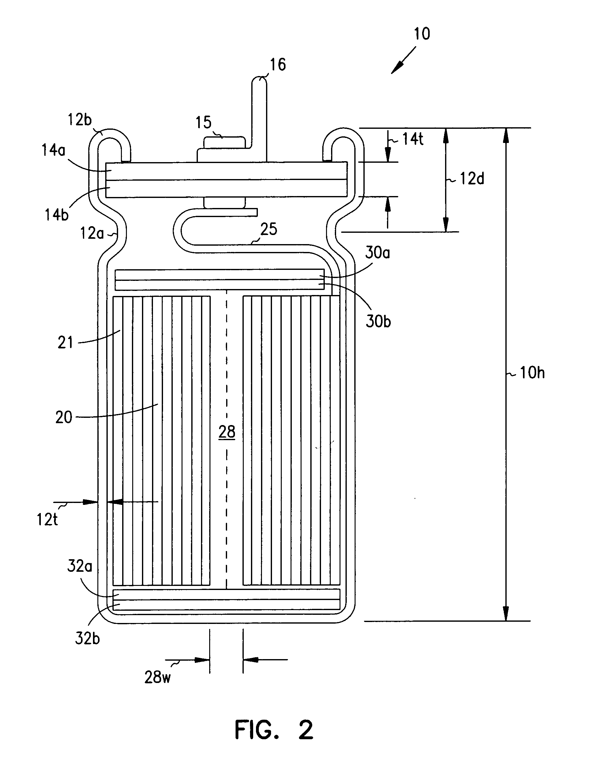
[0026] The following detailed description, which references and incorporates FIGS. 1-6, describes and illustrates one or more specific embodiments of the invention. These embodiments, offered not to limit but only to exemplify and teach, are shown and described in sufficient detail to enable those skilled in the art to implement or practice the invention. Thus, where appropriate to avoid obscuring the invention, the description may omit certain information known to those of skill in the art.

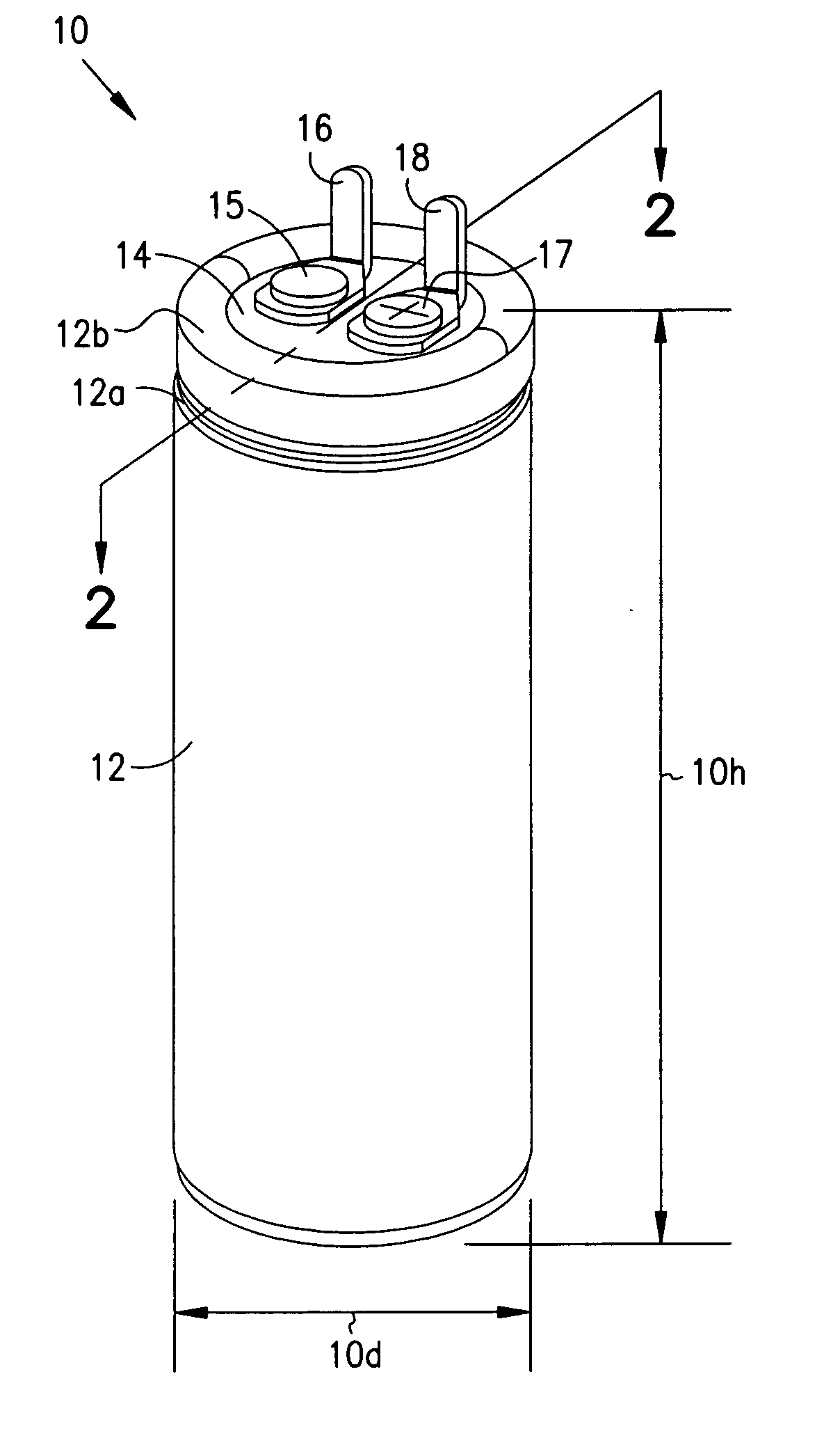
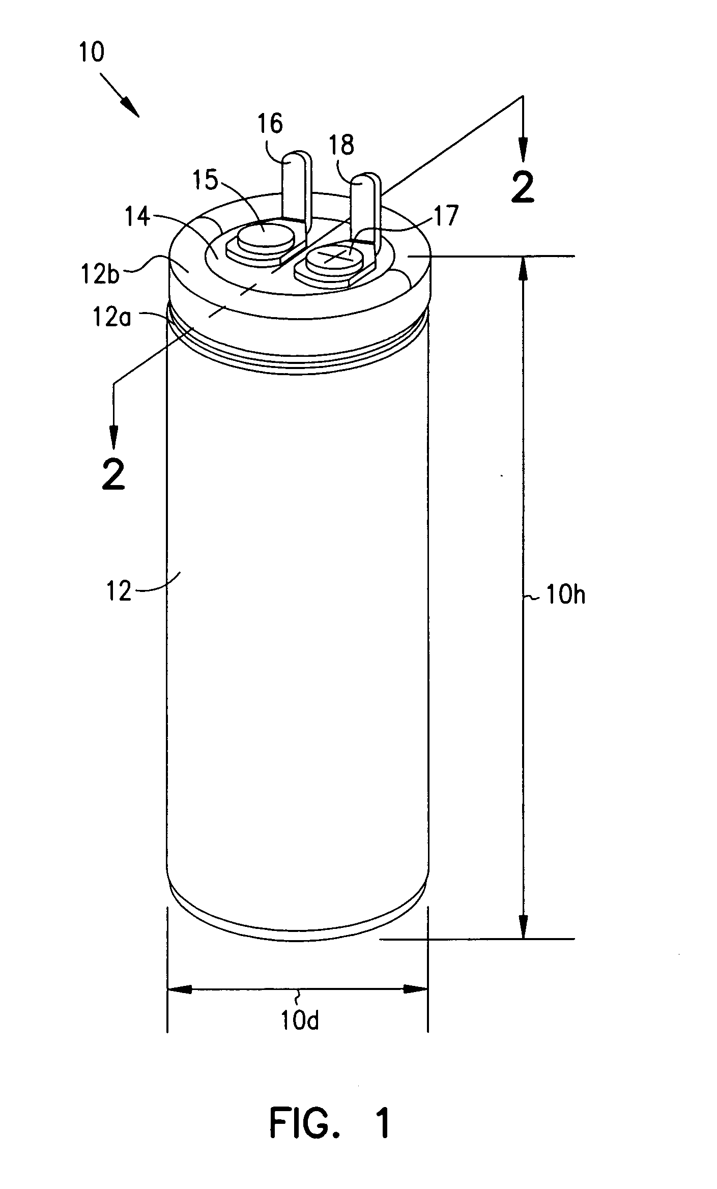
[0027]FIG. 1 shows a perspective view of an exemplary 360-volt operating, 390-volt surge, 190-microfarad, 15.9-Joule (stored) electrolytic capacitor 10 which incorporates various space-saving features of the present invention. Capacitor 10 has a diameter 10d of about 14.5 millimeters and a total height 10h of about 30 millimeters, and a total volume of about five cubic-centimeters. Thus, capacitor 10 has an energy density of about 3.2 Joules per cubic-centimeter.

[0028] In contrast, conventional...


PUM

PropertyMeasurementUnit
thicknessaaaaaaaaaa
thicknessaaaaaaaaaa
thicknessaaaaaaaaaa

Abstract

Implantable defibrillators are implanted into the chests of patients prone to suffering ventricular fibrillation, a potentially fatal heart condition. A critical component in these devices is an aluminum electrolytic capacitors, which stores and delivers one or more life-saving bursts of electric charge to a fibrillating heart. These capacitors make up about one third the total size of the defibrillators. Unfortunately, conventional manufacturers of these capacitors have paid little or no attention to reducing the size of these capacitors through improved capacitor packaging. Accordingly, the inventors contravened several conventional manufacturing principles and practices to devise unique space-saving packaging that allows dramatic size reduction. One embodiment of the invention uses thinner and narrower separators and top and bottom insulative inserts to achieve a 330-volt operating, 390-volt surge, 190-microfarad, 30-Joule aluminum electrolytic capacitor which is 33 percent smaller than conventional capacitors having similar electrical traits.

Description

CROSS-REFERENCE TO RELATED APPLICATION(S) [0001] This application is a continuation of U.S. patent application Ser. No. 10 / 374,668, filed on Feb. 23, 2003, which is a continuation of U.S. patent application Ser. No. 09 / 843,053, filed on Apr. 26, 2001, now issued as U.S. Pat. No. 6,535,374, which is a division of U.S. patent application Ser. No. 09 / 165,848, filed on Oct. 2, 1998, now issued as U.S. Pat. No. 6,275,729, the specifications of which are incorporated herein by reference.BACKGROUND OF THE INVENTION [0002] The present invention concerns electrolytic capacitors, particularly those for use in medical devices, such as implantable defibrillators. [0003] Every year more than half a million people in the United States suffer from heart attacks, more precisely cardiac arrests. Many of these cardiac arrests stem from the heart chaotically twitching, or fibrillating, and thus failing to rhythmically expand and contract as necessary to pump blood. Fibrillation can cause complete loss...

Claims


Application Information

Patent Timeline
Patent Type & Authority Applications(United States)
IPC IPC(8): A61N1/39H01G9/00H01G9/02H01G9/04H01G9/06
CPCA61N1/3975A61N1/3981H01G9/02Y10T29/417H01G9/06H01G9/145H01G9/045
Inventor O'PHELAN, MICHAEL J.POPLETT, JAMES M.TONG, ROBERT R.BARR, ALEXANDER GORDON
Owner CARDIAC PACEMAKERS INC
Why Eureka
Try Eureka