Highly conductive ordered ion exchange membranes

Inactive Publication Date: 2005-10-27
BEN GURION UNIVERSITY OF THE NEGEV
View PDF8 Cites 48 Cited by
  • Summary
  • Abstract
  • Description
  • Claims
  • Application Information

AI Technical Summary

Benefits of technology

[0019] In another process for producing the ordered membranes of this invention the electric field orders a phase or domain of ion or proton conducting or exchange polymers or oligomers, [or a precursor of such a polymers or oligomers], which form due to the incompatibility [phase separation] between the said polymers or oligomers and the material of the matrix. The final membrane that forms upon solvent removal from a wet film or cooling of polymer melt mixtures which causes ionic polymer/oligomers phase separation from the matrix material (which may be polymers that are organic, inorganic or a mixture of both organic or inorganic) resulting in domains or volumes of conducting or ion exchange materials in a matrix. The application of an elec

Problems solved by technology

In fact, the above concentrations are the maximum possible for the ED application: an attempt to increase ion exchanger concentration beyond this range for obtaining higher conductivity results in loss of membrane strength and reduced shape stability due to increased swelling when exposed to salt solutions.
Ho

Method used


Image

  • Highly conductive ordered ion exchange membranes
  • Highly conductive ordered ion exchange membranes
  • Highly conductive ordered ion exchange membranes

Examples


Example

Example 1

[0118] Membrane samples of different cation exchange resin content were prepared by using quantitaties of matrix precursor (two component silicon rubber-RTV) and cation exchange resin powder made of spherical particles 30-40 μm in diameter according to the following Table IV: TABLE IVResin ContentMatrix Precursor (gr)(W %)Component AComponent BResin Powder (gr)100.8110.0890.1150.7720.0780.15200.7270.0730.2300.6360.0640.3400.5450.0550.4500.4550.0450.5

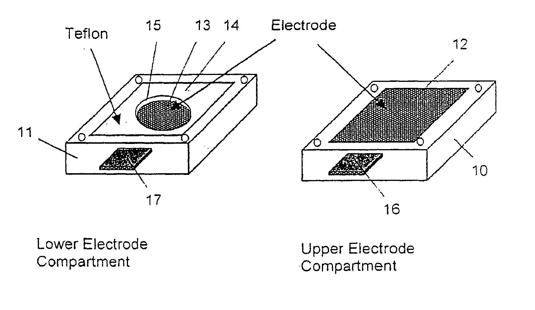
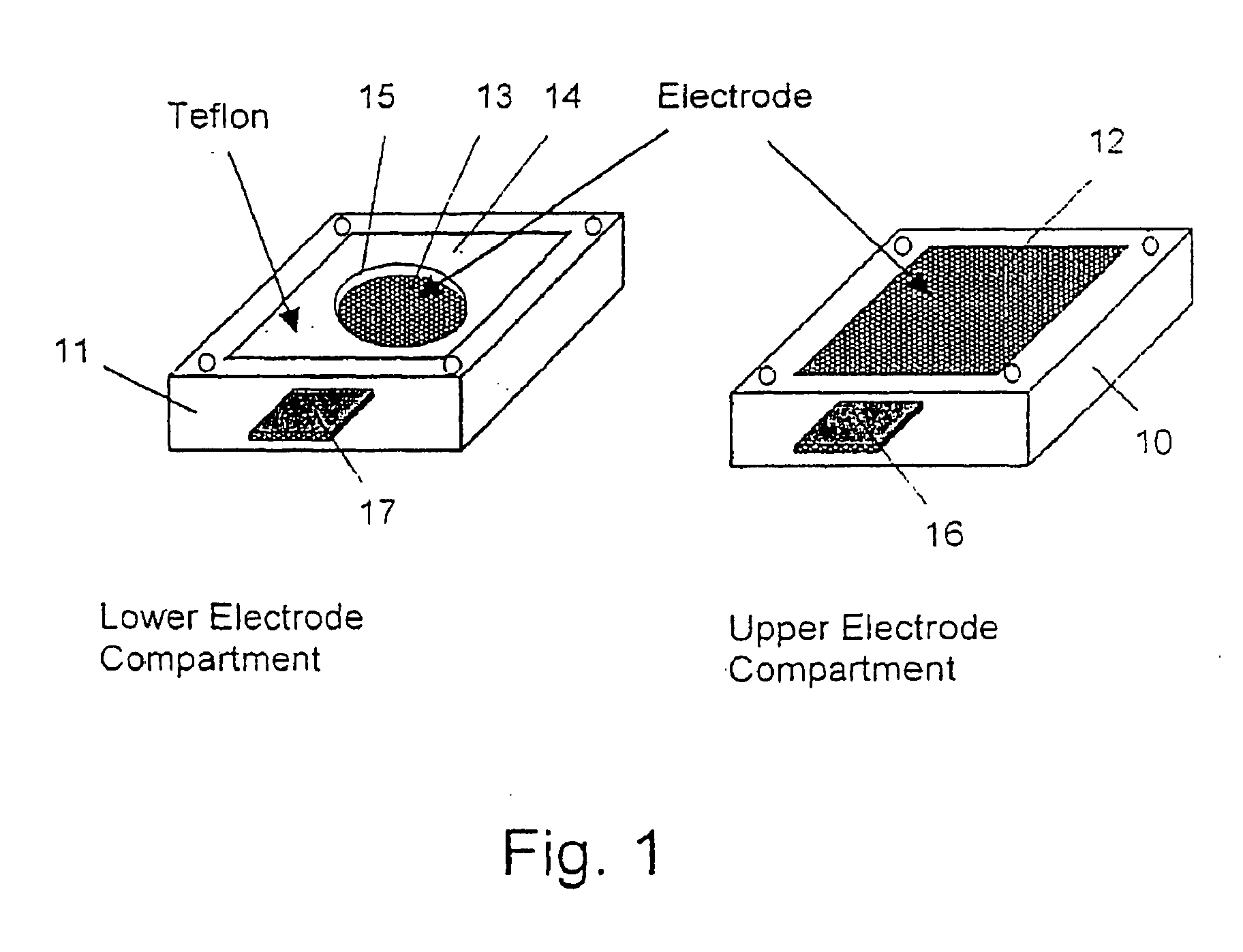
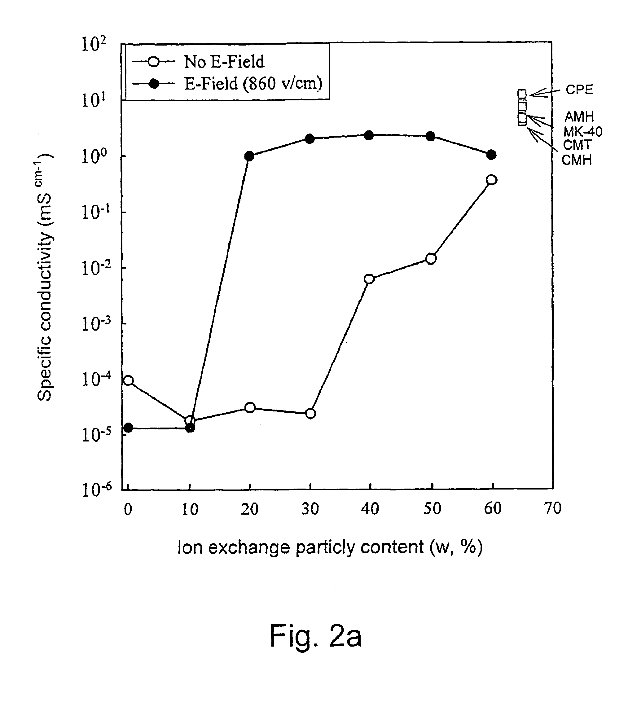
[0119] The components were mixed together and the viscous mixture was poured into the membrane preparation form described in FIG. 1. The cell was closed with the upper electrode module and a 50 Hz AC electric field of strength of 860 V / cm was applied between the electrodes for 4 Hrs at room temperature. The cell was then opened and the cured membrane taken out and equilibrated in 0.1 M KCl solution. The same procedure was applied to a second preparation but without the electric field. The conductivities of the ordered and non-...

Example

Example 2

[0120] The same procedures as in example 1 were applied to a 200 to 270 mesh cation exchange powder with non-spherical particles. The results are depicted in FIG. 2b, with significantly improved conductivity for the ordered membranes compared with the non-ordered ones.

Example

Example 3

[0121] The same procedures as in Example 1 and 2 are applied to powders made of spherical and non-spherical anion exchange resins. As in the previous examples, the ordered anion exchange membrane thus obtained have a much larger specific conductivity as compared to the random ones.


PUM

PropertyMeasurementUnit
Lengthaaaaaaaaaa
Timeaaaaaaaaaa
Diameteraaaaaaaaaa

Abstract

Process for producing ion exchange membranes. A matrix material that comprises a polymeric component chosen from the group consisting of monomeric and oligomeric polymer precursors and cross-linkable polymers is provided. Ion cation or anion exchange particles, or proton or hydroxyl or ion conducting particles, or cation or anion exchange polymers, or proton or hydroxyl or ion conducting polymers are introduced in the matrix. The particles are mixed or the polymer is dissolved with the matrix. The resulting mixture is formed into membrane configuration. The particles or the domains of the polymer formed by polymer-matrix phase separation upon solvent evaporation or cooling, are ordered by an electric field. If the matrix comprises or consists of a polymer precursor or a cross-linkable polymer, the precursor is cured concurrently with the ordering of the particles, or if the matrix comprises a polymer solution or polymer melt the polymer solution is evaporated or the polymer melt is maintained and then cooled concurrently with the ordering of the particles.

Description

FIELD OF THE INVENTION [0001] This invention relates to ion conducting membranes in general, or specifically without limitation ion exchange and / or proton or hydroxyl conducting membranes for use in electrodialysis as ion selective membranes and in power sources such as fuel cells as proton or hydroxyl ion conductive separators. Specifically, this invention relates to a new method for preparing heterogeneous membranes that have a better combination of improved stability, conductivity and / or selectivity than the prior art ones. BACKGROUND OF THE INVENTION [0002] Ion exchange membranes (IEM) are used in electrodialysis (ED) as ion selective membranes and in power sources such as fuel cells as proton conductive separators. Basically, two types of IEMs for use in ED are available: homogeneous, that is composed of a cross-linked polymer, which is chemically treated to bind ion exchange groups onto its skeleton. The other type, heterogeneous IEM, are prepared by random filling of a neutra...

Claims


Application Information

Patent Timeline
IPC IPC(8): B01D61/44B01D61/52B01D63/08B01D67/00B01D69/14B01D71/26B01D71/30B01D71/32B01D71/34B01D71/36B01D71/56B01D71/70B01D71/80B01D71/82B01J39/00B01J41/00B01J47/12C08J5/22H01M8/10
CPCB01D61/44C08J2327/18B01D63/081B01D67/0011B01D67/0013B01D69/141B01D71/26B01D71/30B01D71/32B01D71/34B01D71/36B01D71/56B01D71/70B01D71/80B01D71/82B01J47/12C08J5/22C08J5/2237H01M8/1044H01M8/106H01M8/1072H01M8/1081H01M2300/0082Y02E60/523B01D2325/24B01D2325/26B01D2325/30B01D2325/42B01D2323/35B01D63/02B01D63/06B01D2313/365B01D61/52Y02E60/50Y02P70/50
Inventor OREN, YORAMFREGER, VIATCHESLAVKEDEM, ORALINDER, CHARLES
Owner BEN GURION UNIVERSITY OF THE NEGEV
Why Eureka
Try Eureka