Thermal sensing device for thermal mapping of a body conduit

a sensing device and thermal mapping technology, applied in the direction of surgical instruments for cooling, therapeutic heating, therapeutic cooling, etc., can solve the problems of blood vessels subjected to angioplastic treatment having a marked tendency to undergo restnosis, evaporative cooling is not amenable to precise control of cooling process, and implementations described are limited to cryogenic cooling, etc., to achieve accurate control of balloon temperature, increase pressure, and high uniform distribution of cold

Inactive Publication Date: 2005-10-27
GALIL MEDICAL
View PDF66 Cites 20 Cited by
  • Summary
  • Abstract
  • Description
  • Claims
  • Application Information

AI Technical Summary

Benefits of technology

[0038] According to further features in preferred embodiments of the invention described below, the plurality of thermal sensors are distributed along an expandable spiral sensing loop having a distal end anchored to a distal portion of the catheter, the sensing loop being spirally wound around a section of shaft of the catheter and being operable to expand away from the shaft, thereby enhancing thermal communication between the sensors distributed along the sensing loop and body tissues adjacent to the catheter.
[0091] The present invention further successfully addresses the shortcomings of the presently known configurations by providing a system for detecting a leak in a balloon angioplasty system, which detection is highly sensitive to even very small leaks in an inner angioplasty balloon, thereby enabling to immediately cease supply of input fluids, and to undertake other or additional corrective measures, as soon as such a very small leak is detected, and without necessitating waiting for a leak large enough to significantly raise pressure in an outer balloon volume.

Problems solved by technology

It is a well-known problem of angioplastic surgery that blood vessels having been subjected to angioplastic treatment have a marked tendency to undergo restenosis.
It is, however, a limitation of the above-mentioned Lafontaine patents and patent application that the implementations described are limited to cryogenic cooling by evaporation of a liquid.
Further, evaporative cooling is not amenable to exact control of the cooling process, because evaporation is not instantaneous.
Introducing into an angioplasty balloon a liquid which cools by evaporation inevitably introduces an intrinsic lag in any possible control of the cooling process, because halting the supply of cooling fluid does not immediately halt cooling.
Joye describes the difficulty of achieving an optimal cooling temperature at a target region, and further describes the difficulty of achieving an even cooling distribution throughout a target region.
Joye does not, however, provide a method of achieving exact control of cooling within the target regions.
This link, between pressure of gas within an inflated balloon and the amount of cooling of that balloon, is one of the disadvantages of using an evaporation process to achieve cryogenic cooling of an angioplasty balloon.
With respect to the well-known difficulty of achieving an even cooling distribution throughout a target region, Joye discusses the fact that evaporative cooling tends to cool an apparatus unevenly, parts of the apparatus adjacent to a lumen through which cooling fluid is supplied being significantly colder than more distant parts of the apparatus.
We note, however, a disadvantage of the described safety interlock system, in that it is designed to detect such a leak only after a significant rise in pressure has occurred within the outer balloon.
Referring now to other aspects of prior art, it is noted that one of the basic problems inherent in angioplasty and similar surgical interventions is the need to effect correct placement of an angioplasty balloon catheter prior to performance of angioplasty.

Method used


Image

  • Thermal sensing device for thermal mapping of a body conduit
  • Thermal sensing device for thermal mapping of a body conduit
  • Thermal sensing device for thermal mapping of a body conduit

Examples


Embodiment Construction

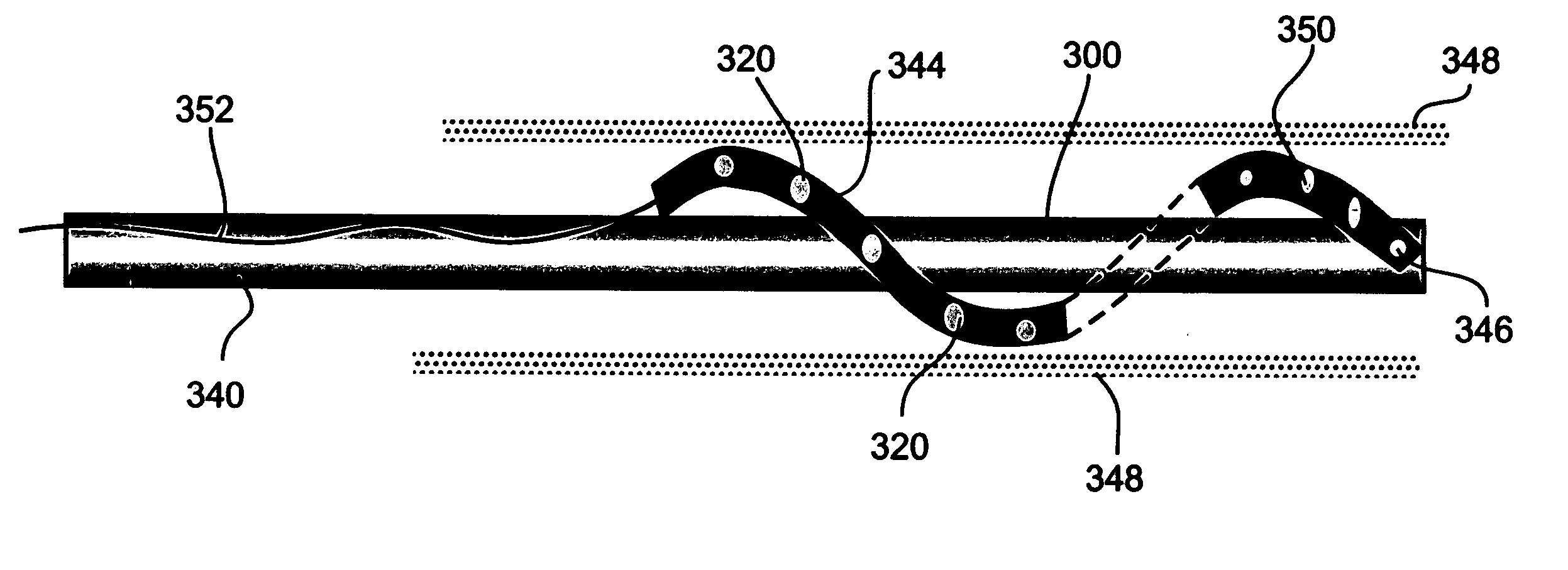
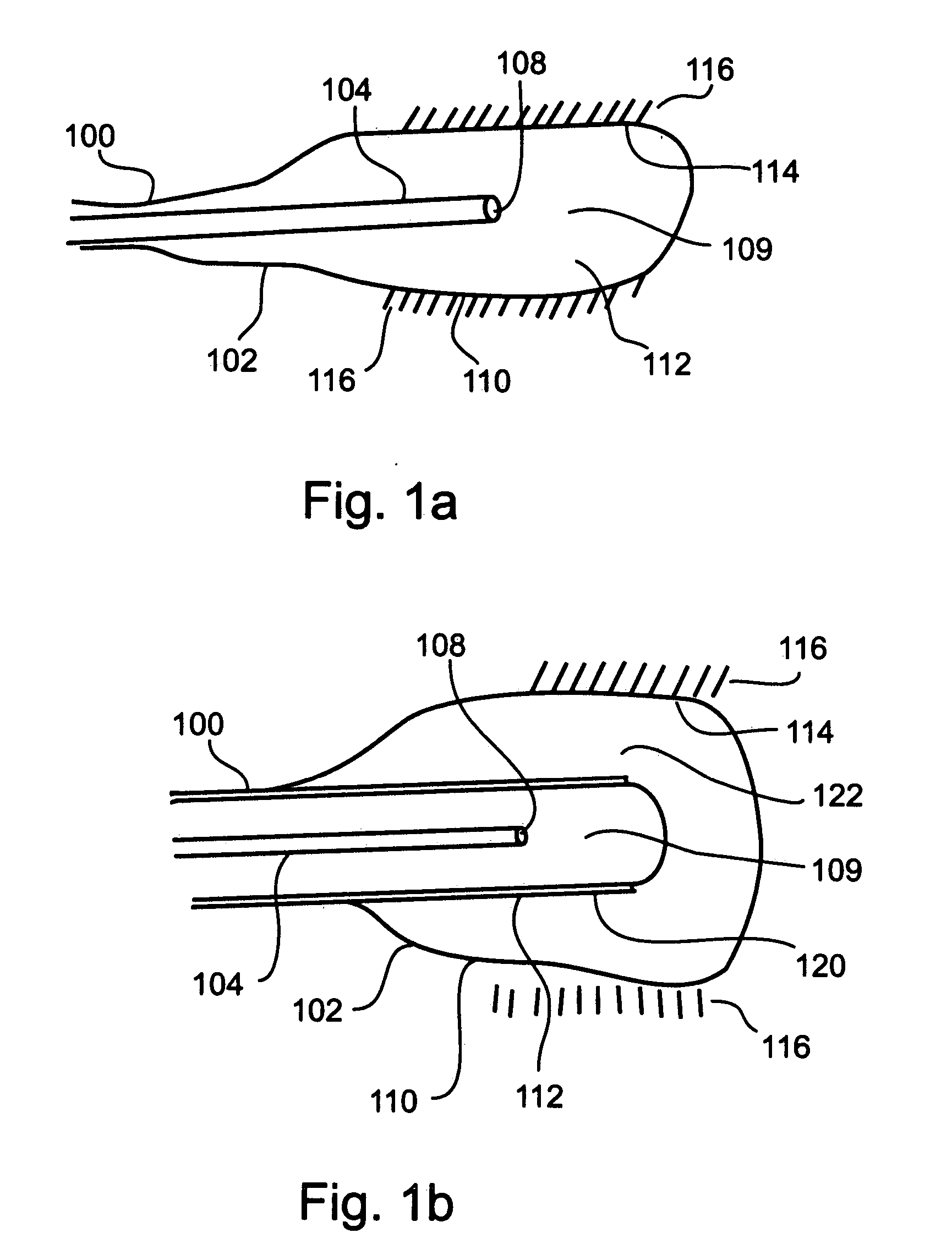
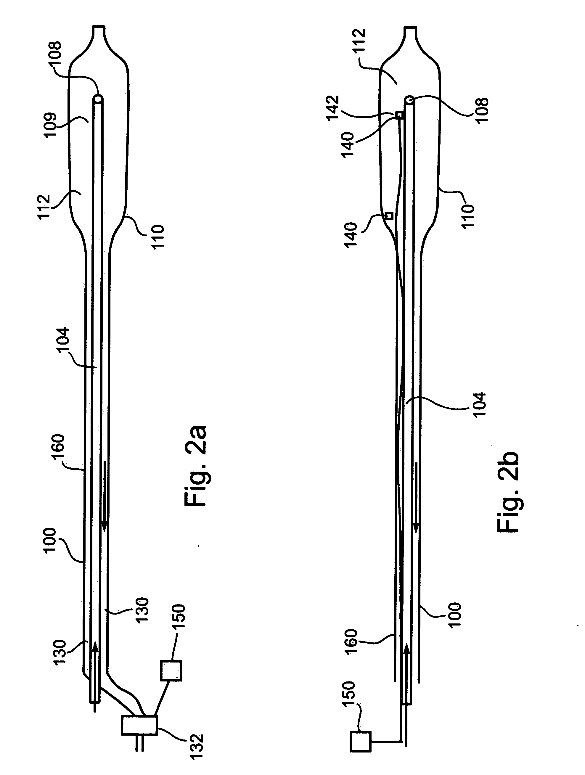
[0122] The present invention is of an angioplasty balloon catheter operable to utilize compressed gas for direct Joule-Thomson cooling of an angioplasty balloon with a high degree of temperature control, and having a plurality of temperature sensors operable to measure temperatures at a variety of locations within an artery, thereby providing information permitting to identify a locus for placement of an angioplasty balloon for treatment of arterial stenosis.

[0123] Specifically, the present invention can be used to accurately place an angioplasty balloon in a position appropriate for balloon angioplasty treatment of stenosis, and to directly cool an angioplasty balloon during use in treatment of stenosis, thereby discouraging or preventing restenosis.

[0124] The principles and operation of a cryogenic angioplasty balloon catheter according to the present invention may be better understood with reference to the drawings and accompanying descriptions.

[0125] Before explaining at leas...


PUM


Abstract

The present invention relates to apparatus, systems, and methods utilizing cryogenic cooling in an angioplasty balloon catheter for treatment of arterial stenosis and prevention of restenosis. More particularly, the present invention relates to an angioplasty balloon catheter utilizing expansion of compressed gas to effect Joule-Thomson cooling of an angioplasty balloon, and optionally further incorporating external temperature sensors utilizable to identify a locus for treatment of arterial stenosis. The present invention further relates to angioplasty treatment systems incorporating such a catheter, and to cryogenic angioplasty methods for treating arterial stenosis and discouraging restenosis.

Description

[0001] This application is a divisional of U.S. patent application Ser. No. 11 / 097,306, filed Apr. 4, 2005, which is a divisional of U.S. patent application Ser. No. 10 / 255,834, filed Sep. 27, 2002, now U.S. Pat. No. 6,875,209, issued Apr. 5, 2005, which claims the benefit of priority from U.S. Provisional Patent Application No. 60 / 357,653, filed Feb. 20, 2002, and U.S. Provisional Patent Application No. 60 / 324,937, filed Sep. 27, 2001, the contents thereof are incorporated herein by reference.FIELD AND BACKGROUND OF THE INVENTION [0002] The present invention relates to apparatus, systems, and methods utilizing cryogenic cooling in an angioplasty balloon catheter for treatment of arterial stenosis and prevention of restenosis. More particularly, the present invention relates to an angioplasty balloon catheter utilizing expansion of compressed gas to effect Joule-Thomson cooling of an angioplasty balloon, and optionally further incorporating external temperature sensors utilizable to...

Claims


Application Information

Patent Timeline
Patent Type & Authority Applications(United States)
IPC IPC(8): A61F7/00A61B17/00A61B17/22A61B17/42A61B17/46A61B18/02A61B18/18A61D1/10A61F7/12A61M25/00F25B9/02F25B19/02
CPCA61B2018/00041A61B2018/0022A61B2018/0212A61B2018/0262A61B2017/22051A61B18/02A61B2017/00084A61B2017/00101A61B2017/22002F25B9/02
Inventor ZVULONI, RONIBLIWEIS, MORDECHAISCHECHTER, DORISAMIR, URIMCGLONE, JAMES
Owner GALIL MEDICAL
Why Eureka
Try Eureka