Thermoelectric Module

Inactive Publication Date: 2005-11-03
KYOCERA CORP
View PDF5 Cites 90 Cited by
  • Summary
  • Abstract
  • Description
  • Claims
  • Application Information

AI Technical Summary

Benefits of technology

[0061] Further, the block electrode is preferably a metal containing at least one element selected from among Zn, Al, Au, Ag, W, Ti, Fe, Cu, Ni and Mg. This enables it to provide the block electrode of lower resistance and lower power consumption.
[0062] Further it is preferable that the ratio of maximum diameter to height of the block electrode is in a range from 0.2 to 20. This constitution reduces the problems of breakage or bending of the electrode or peel-off of the joint during wire bonding, and makes it easier to improve the perpendicularity and straightness, thereby to improve the yield of production.
[0063] It is preferable that the melting temperature of the solder that bonds the planar electrode and the block electrode and the melting temperature of the solder that bonds the thermoelectric element and the wiring conductor are different. This makes it easier to assemble by taking advan

Problems solved by technology

However, performance of the conventional thermoelectric module has been limited in order to meet these requirements.
But the conventional thermoelectric module sometimes fails to pass reliability tests for shock, energization cycles, high-temperature operation, etc.
Failure to pass the reliability tests occurs from various causes such as deterioration of the thermoelectric elements, deterioration of joint between the thermoelectric elements and the wiring conductor and dete

Method used


Image

  • Thermoelectric Module
  • Thermoelectric Module
  • Thermoelectric Module

Examples


embodiment 1

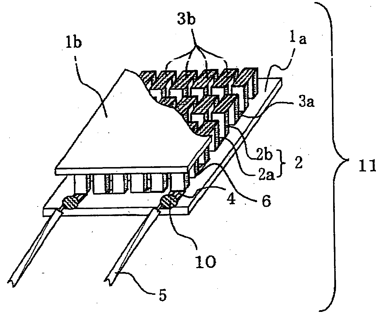
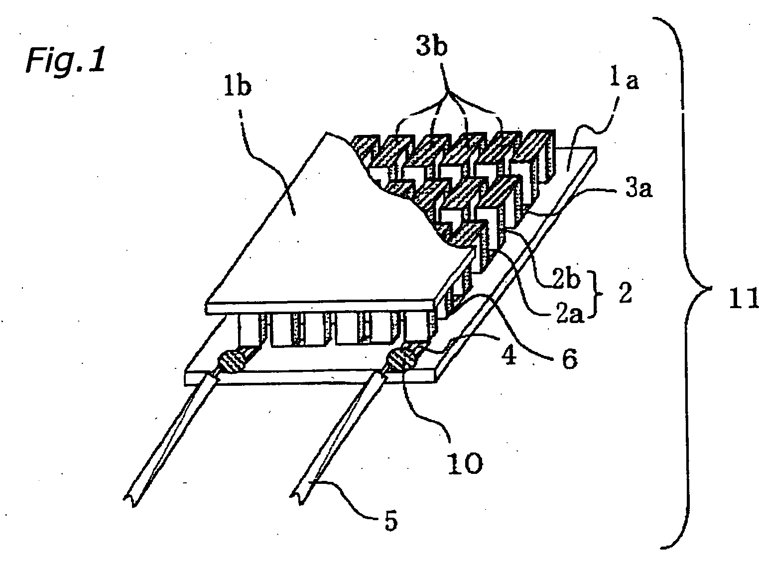
[0078] This embodiment is a thermoelectric module where a P-type thermoelectric element and an N-type thermoelectric element have different values of resistivity. A case where the lead member is a lead wire as shown in FIG. 1 will be described as an example.

[0079] The thermoelectric module shown in FIG. 1 comprises support substrates 1a, 1b made of ceramics such as alumina or an insulating resin, an N-type thermoelectric element 2a and a P-type thermoelectric element 2b that are disposed in the same numbers on the support substrates 1a, 1b, wiring conductors 3a, 3b that connect the plurality of thermoelectric elements in series with each other, and external connection terminal 4 provided on the support substrates 1a, 1b and are electrically connected to the wiring conductors 3a, 3b. The external connection terminal 4 can be connected with a lead wire 5 by means of solder 6. Power is supplied from the outside via the lead wire 5 connected to the external connection terminal 4.

[0080...

embodiment 2

[0101] The thermoelectric module of this embodiment is a variation of the thermoelectric module of the first embodiment where the wiring conductor is formed in a predetermined shape so as to further improve the reliability of the thermoelectric module. With other respects, this embodiment is similar to the first embodiment.

[0102] In the prior art, there has been the wiring conductor 3 having D-shaped cross section as shown in FIG. 4A. As a consequence, when the thermoelectric elements 2 is displaced from the center of the wiring conductor 3, a gap is formed between the bottom surface of the thermoelectric elements 2 and the top surface of the wiring conductor 3 (element bonding surface), resulting in lower reliability. According to this embodiment, to counter the problem described above, the wiring conductor 3 is formed so as to have a cross section of rectangular, square or trapezoidal shape which is longer on the element bonding surface side (inverted trapezoid). FIG. 3A shows a ...

embodiment 3

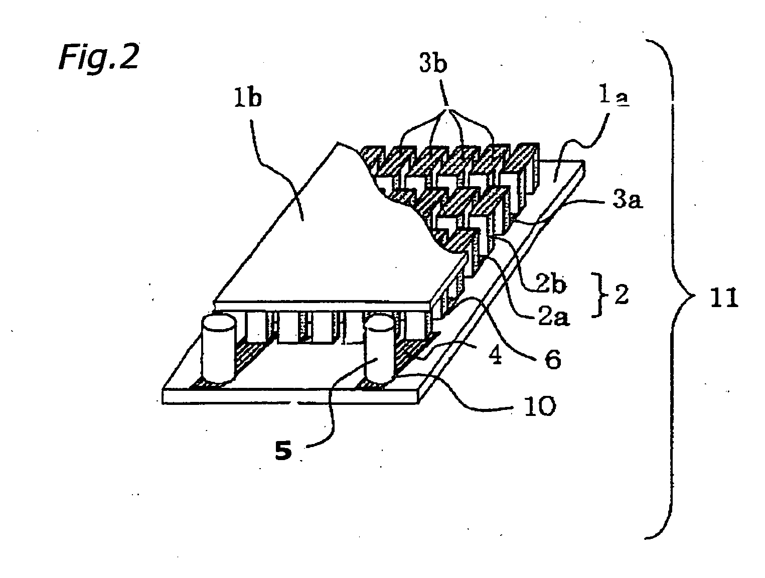
[0113] This embodiment is a variation of the thermoelectric module of the first or second embodiment where composition of the solder 10 that connects the lead member 5 with the external connection terminal is controlled so as to improve the reliability of the thermoelectric module further. With other respects, this embodiment is similar to the first and second embodiment.

[0114] In this embodiment, Sn content in the solder 10 that connects the lead member 5 with the external connection terminal is controlled in a range from 12% to 40% by weight. There are no restrictions on the content of other component, as long as the Sn content is within this range. When the Sn content is less than 12% by weight, melting point of the solder becomes too high which results in melting or deterioration of the element, thus making it impossible to make a good joint. When the Sn content is higher than 40% by weight, the higher proportion of Sn in the solder increases the possibility of reaction with th...


PUM


Abstract

A thermoelectric module 11 includes support substrates 1a and 1b, the same numbers of N-type thermoelectric elements 2a and P-type thermoelectric elements 2b disposed on the support substrates 1a and 1b, wiring conductors 3a and 3b that electrically connect between the thermoelectric elements in series and an external connection terminal 4 electrically connected to the wiring conductor 3a. The N-type thermoelectric elements 2a and the P-type thermoelectric elements 2b have different values of resistivity.

Description

BACKGROUND OF THE INVENTION [0001] 1. Field of the Invention [0002] The present invention relates to a thermoelectric module that is preferably used in applications of temperature control, keeping coolness and power generation. [0003] 2. Description of the Related Art [0004] A thermoelectric element is based on the Peltier effect in that a PN junction device comprising a P-type semiconductor and an N-type semiconductor, with current flowing therethrough, generates heat at one end and absorbs heat at the other end. A thermoelectric module that embodies the Peltier effect in a module is capable of precise temperature control, and is small in size and simple in construction. As such, the thermoelectric module has the potential for practical use in wide applications such as refrigeration apparatus that does not use flon, photo detector device, electronic cooling device for semiconductor manufacturing apparatus and temperature control for laser diode. The thermoelectric element also show...

Claims


Application Information

Patent Timeline
IPC IPC(8): H01L35/00H01L35/04H01L35/08H01L35/10H01L35/28H01L35/34H01L37/00
CPCH01L35/10H01L35/08H10N10/82H10N10/817
Inventor TAJIMA, KENICHITANAKA, KOICHI
Owner KYOCERA CORP
Why Eureka
Try Eureka