Vibrating, magnetically guidable catheter with magnetic powder commingled with resin, extruded as an integral part the catheter

a technology of magnetic powder and resin, which is applied in the field of catheters, can solve the problems of entire wires vibrating, and stiffness acting adversely

Inactive Publication Date: 2005-11-03
CASEY DON EWARD
View PDF9 Cites 120 Cited by
  • Summary
  • Abstract
  • Description
  • Claims
  • Application Information

AI Technical Summary

Benefits of technology

[0005] One: The placement of an induction coil emanating a pulsating (half-wave) d.c. or a full wave a.c. field, which can be widely varied in frequency and intensity (voltage), is placed alongside the patient's body, but not attached thereto, while the patient is lying on an operating table, creating what is called a sympathetic vibration of the catheter along its entire length while it is being inserted, preventing accumulative adhesion to the wall of the vasculature while it is being advanced to a blockage site. This coil is attached to a frequency converter electronic device which powers the coil. The fact that catheters vary in 
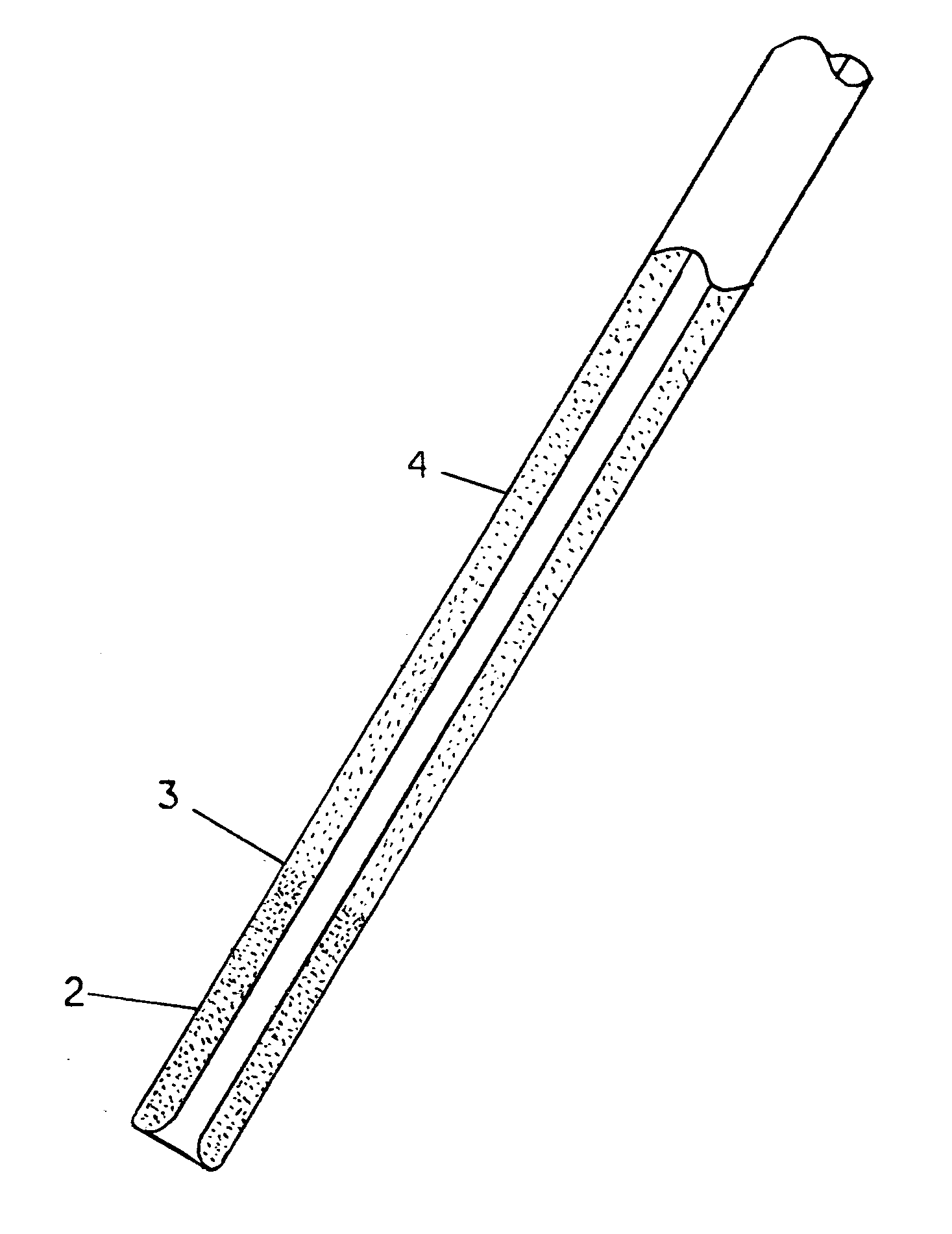
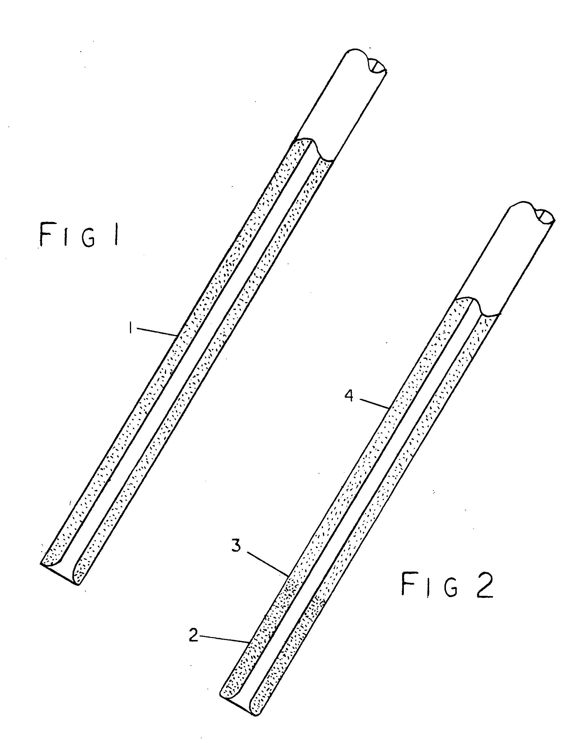
diameter from about 0.040″ inches down to 0.015″ inches means they have relatively little longitudinal stiffness, although presently the 0.015″ diameter catheters tend to be about a foot in length, mainly for insertion via the carotid artery in the neck and advanced to a location in the brain. Although it is true that the insertion of a “J” wire gives catheters stiffness, this stiffness acts adversely when the catheter needs to follow a circuitous pathway to reach a blockage site, typically found near the terminus of an artery, where the arterial wall is thin and subject to easy damage by perforation by the “J” wire.
[0007] This a.c. or half-wave pulsating d.c. powered coil will have a truncated cone affixed to one side, with sufficiently thick iron construction so that the cone does not vibrate and impart vibrations into the body, but serves only as a shunt, focusing the vibratory field of the coil so vibrations will pass through the narrow, truncated open end of the cone, vibrating only the distal tip of the catheter or that part where a concentration of vibrations is desired, while keeping a cardiac pacemaker that may be implanted close to the patient's heart, shielded. It is known in the literature regarding magnetic fields that there are two barriers to bar a magnetic field: One is simply air space or distance, the second is iron, which tends to act as a shunt or absorbing barrier to such a field. In fact, when rare earth magnets are shipped by common carrier, they are classified as “Hazardous Cargo,” and must be positioned in the center of an outer steel (iron) cage or box within an outer shipping container, to provide magnetic isolation. The coil is designed so that either the open or the cone-shaped side can face toward the patient's body, or held by a technician, so the entire catheter will vibrate while it is being inserted and guided to the blockage site, then by flipping over the coil, only a portion of the forward portion of a catheter will vibrate. When the catheter has reached the blockage site, the coil can be repositioned so its cone side is facing toward the distal tip of the catheter, which is being continuously viewed with the aid of a fluoroscopic or an ultra-sound machine, each machine having advantages with regard to looking inside the body: Fluoroscopic machines (weak x-rays) can see through bones and vacant space (lungs); whereas, ultra sound machines can be positioned to “see” between bones such as ribs, and can view in false coloring, and adjusted to view only to a pre-set depth within the body, minimizing screen clutter.
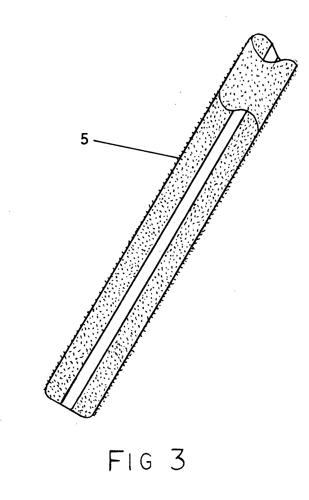
[0009] However, this design calls for another guidance method not requiring the “J” wire. The magnetic powder impregnated into the catheter wall allows the catheter to be guided by an external, hand-held magnetic guiding device. This hand-held guider (to be discussed in a separate application) with its magnets positioned close to the body, obviates the need for giant magnetic fields created by very large electro-magnetic coils, as shown in Stereotaxis and other patents regarding this subject area. All magnetic fields drop off dramatically (at a non-linear rate) as their distance is increased from another magnet or magnetically responsive metal. Therefore, a magnetic field positioned very close to the body will not have to be nearly as powerful. It should also be noted that non-magnetic metals, such as Nitinol, may also be used in this catheter, however, such a catheter will not be nearly as responsive to an external magnetic field.

Problems solved by technology

Although it is true that the insertion of a “J” wire gives catheters stiffness, this stiffness acts adversely when the catheter needs to follow a circuitous pathway to reach a blockage site, typically found near the terminus of an artery, where the arterial wall is thin and subject to easy damage by perforation by the “J” wire.
Prior art shows one or two patents in which a vibrating device is attached to the “J” wire, causing the entire wire to vibrate as a way to loosen plaque, which is not a good idea, because the suction pump can not withdraw plaque while the “J” wire blocks the lumen.

Method used


Image

  • Vibrating, magnetically guidable catheter with magnetic powder commingled with resin, extruded as an integral part the catheter
  • Vibrating, magnetically guidable catheter with magnetic powder commingled with resin, extruded as an integral part the catheter
  • Vibrating, magnetically guidable catheter with magnetic powder commingled with resin, extruded as an integral part the catheter

Examples


Embodiment Construction

[0020] The first embodiment of this invention shown in FIG. 1, numeral 1 highlights the elegant simplicity of this design over prior art showing rare-earth or (Alinco-ceramic, etc.) magnetic powder or more common metals impregnated into the resin, in the tube extrusion machine in various densities and shapes, before or as the catheter is extruded, making the powder an integral part of the catheter, not subject to separation from the catheter as is the case with magnets variously attached, after it has been extruded. This integral incorporation of magnetic powder is highly desirable over the use of separate magnets shown in other patents attached to the catheters, usually by surgical adhesive or wire in the case of magnets attached to the distal tip, because magnetic powder tends not to maintain good shape integrity. It tends to crumble and return to a powdered state, especially when subject to vibrations, as this catheter is designed to be. Rare Earth magnets, usually made of alloys...


PUM


Abstract

A catheter that is produced in which magnetic powder is commingled and becomes an integral part of the catheter, which makes it not only guidable within the body by an external device, but can be made to vibrate at various speeds (cycles per second) and at varying intensities (voltages) to not only prevent its adhesion to vascular walls, but to render plaque into a viscous state, for easy suctioning from the body.

Description

FIELD OF THE INVENTION [0001] This invention relates to catheters, in particular to a manufactured catheter in which magnetic powder is mixed with the resin and extruded as an integral part of the catheter. BACKGROUND OF THE INVENTION [0002] Prior art shows conventional magnetic catheters designed so that magnet(s), made in various shapes, are attached to the catheter after the catheter has been formed by a tube extrusion machine. These magnets typically take one of two shapes: A tubular distal (forward) tip affixed by various attachment methods to the distal end of a catheter for the purpose of guiding and-or pulling the catheter from its advancing end, addressing the problem of catheters lacking longitudinal stiffness when advanced from the proximal (trailing) end, without what is commonly known as a “J” wire inserted into and running through the catheter's lumen or hollow center. [0003] The second design is for magnets to be compression molded as short, thin-walled sleeves or rin...

Claims


Application Information

Patent Timeline
Patent Type & Authority Applications(United States)
IPC IPC(8): A61B5/00A61M25/01
CPCA61M25/0127
Inventor CASEY, DON EWARD
Owner CASEY DON EWARD
Why Eureka
Try Eureka