Transmitting and receiving device

a technology of transmitting and receiving device and receiving device, which is applied in the field of data transmission units, can solve the problems of unwanted delays in the flow of information, examination involves a considerable amount of time expenditure for the physician and the patient, and limitations in mobility and quality of life, and achieves a high degree of flexibility and is cheap to produ

Inactive Publication Date: 2005-11-03
BIOTRONIX CRM PATENT AG
View PDF12 Cites 39 Cited by
  • Summary
  • Abstract
  • Description
  • Claims
  • Application Information

AI Technical Summary

Benefits of technology

[0011] In accordance with certain embodiments of the present invention, a data transmission unit is provided which permits communication between an electromedical implant and a home monitoring service center, but which in that respect signifies for the patient a lesser detrimental effect in respect of his quality of life and which is less ...

Problems solved by technology

In critical situations, that can result in unwanted delays in the flow of information.
In addition, any examination involves a considerable amount of time expenditure for the physician and the patient.
Frequent examinations result in limitations in terms of mobility and quality of life in particular for the patient.
That results in a patient device of relatively large dimensions which can only be used for medical-technical home monitoring of the patient or his electromedical implant.
Now, there is the problem that the patient always has to have about his person a relatively unwieldy device.
Experience with looking after risk patients has shown that, in spite of its possibly life-saving significance, the device is frequently forgotten an...

Method used


Image

  • Transmitting and receiving device
  • Transmitting and receiving device
  • Transmitting and receiving device

Examples


Embodiment Construction

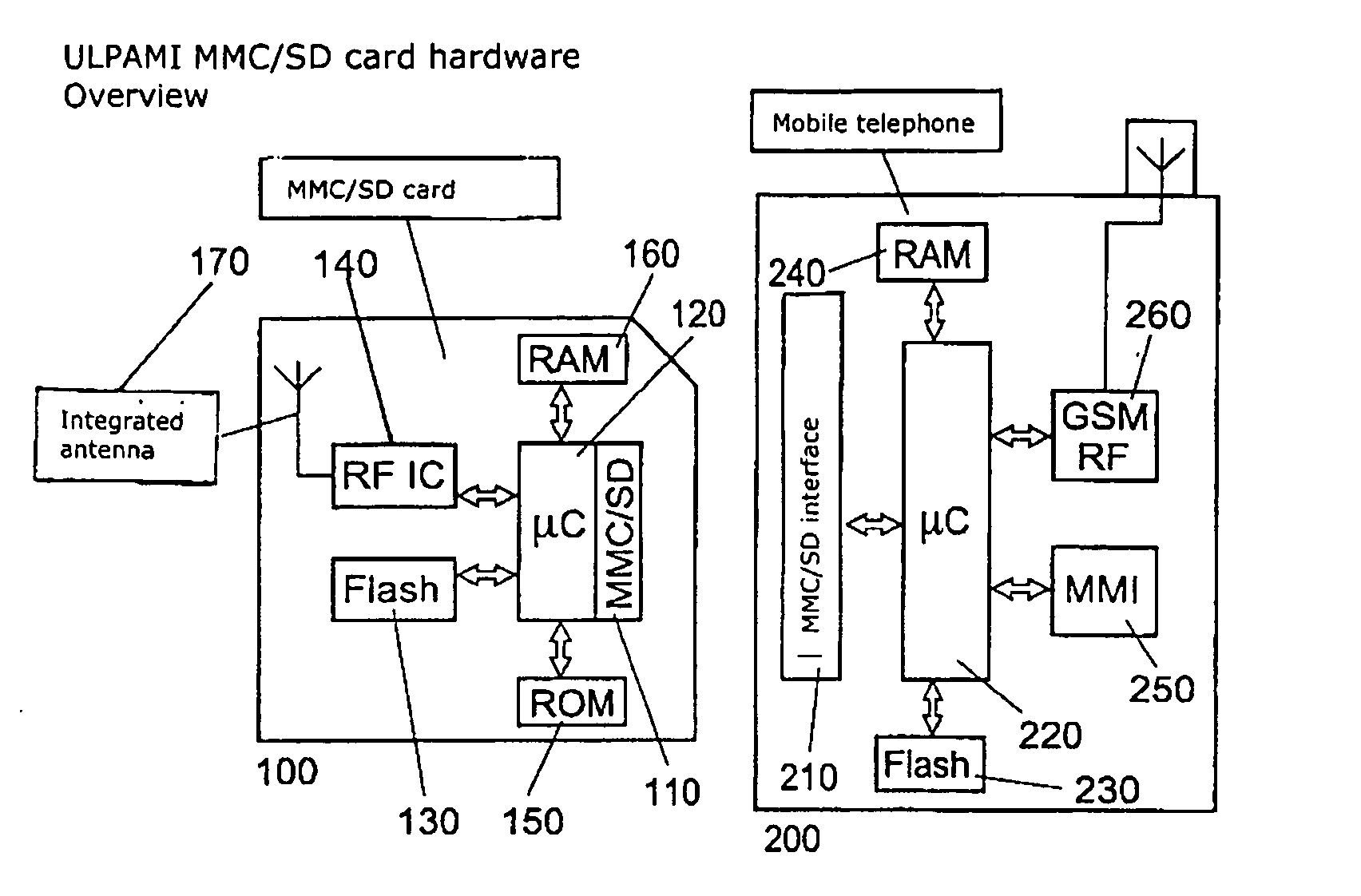
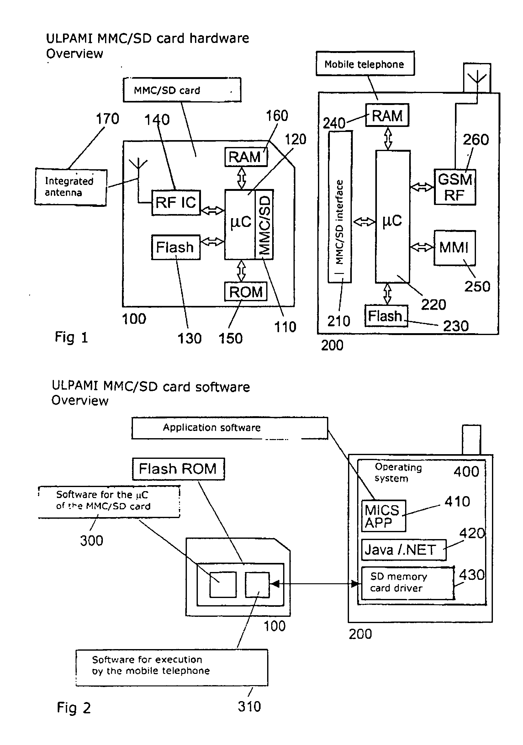
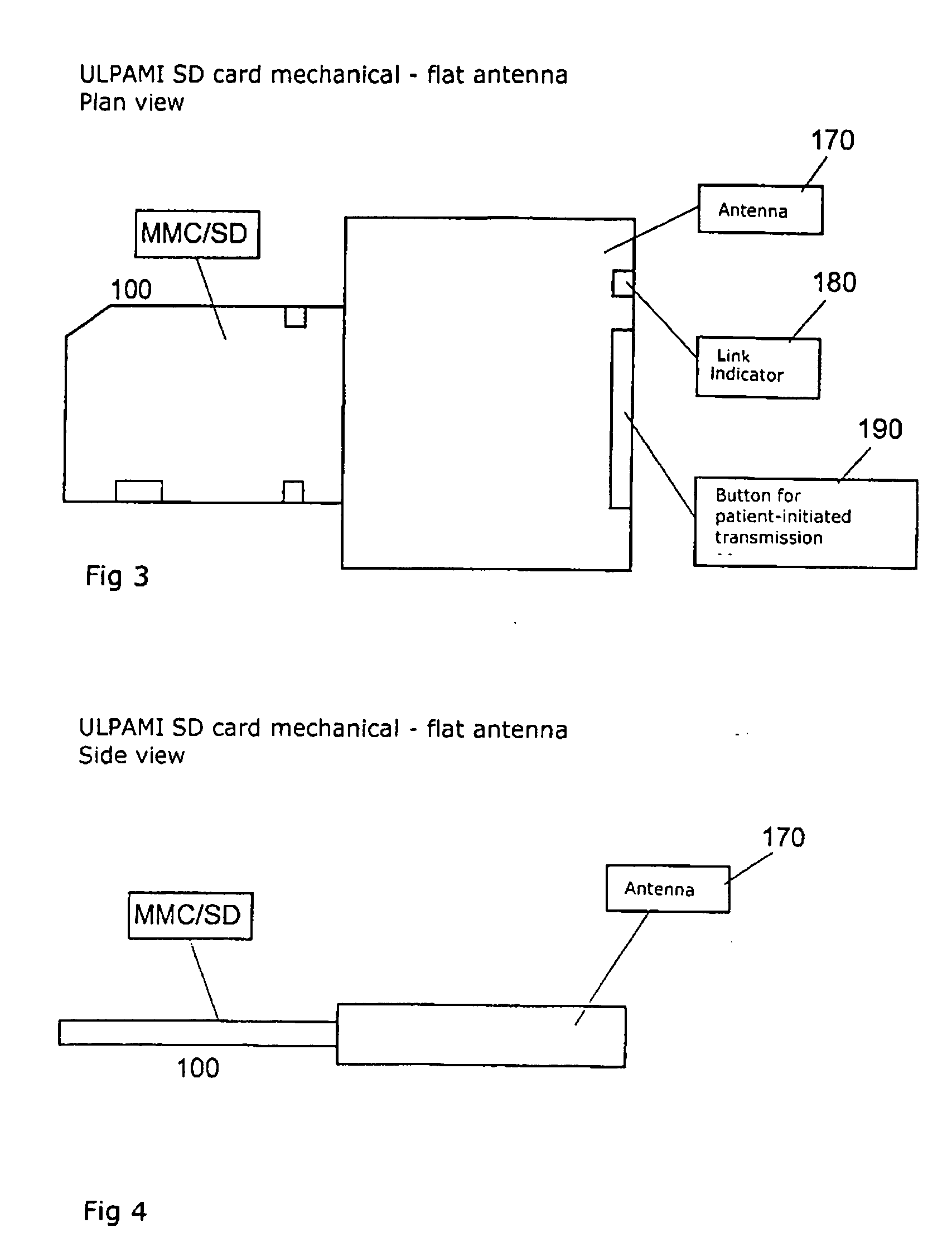
[0044]FIG. 1 shows block diagrams of an electronic plug-in card 100 in accordance with the MMC and SD standards (at the left) and a mobile telephone 200 (at the right). The dimensions of MMC and SD cards are similar or identical so that many mobile telephones can accommodate MMC and SD cards by way of the same slot. The MMC / SD card 100 includes an antenna 170, a RAM 160, a ROM 150, a wireless data interface component 140, a write / read data memory 130 in the form of a non-volatile flash memory, a control unit 120 and a wired interface 110, which are illustrated in FIG. 1 by seven corresponding blocks. The wireless data interface component 140 includes the components required for communication with electromedical implants. The block identified by “μC” includes a programmable control unit 120 which is in the form of a microcontroller and which performs various control tasks on the MMC / SD card. Thus, it controls, in particular also, data exchange by way of the wired interface 110 identi...


PUM


Abstract

Certain embodiments of the present invention disclose a data transmission unit for wireless communication with an electromedical implant and a data acquisition and evaluation center (home monitoring service center) wherein the data transmission unit is an electronic plug-in card which can be inserted into a base device, in particular into a mobile telephone, and which has at least a wireless data interface for the exchange of information with an electromedical implant, a wired data interface with the base device for the exchange of information between the plug-in card and the base device, at least one control unit for controlling the exchange of data by way of at least the wireless data interface, and a write/read data memory which is readable by the base device by way of the wired data interface, wherein the control unit is adapted to write data received from an external device by way of the wireless data interface into the write/read data memory.

Description

CROSS-REFERENCE TO RELATED APPLICATIONS / INCORPORATION BY REFERENCE [0001] This application claims priority to German patent application serial number 10 2004 023 654.2 filed on Apr. 30, 2004, which is incorporated herein by reference in its entirety. This application also claims priority to German patent application serial number 10 2004 043 210.4 filed on Sep. 3, 2004, which is incorporated herein by reference in its entirety. TECHNICAL FIELD [0002] Embodiments of the present invention relate to a data transmission unit. In particular, certain embodiments of the present invention concern a data transmission unit for a patient device for wireless communication with an electromedical implant and a data acquisition and evaluation center (e.g., a home monitoring service center). BACKGROUND OF THE INVENTION [0003] Modern electromedical implants, in particular cardiac pacemakers, defibrillators and the like, offer a physician and patients a very high degree of security and comfort by mea...

Claims


Application Information

Patent Timeline
IPC IPC(8): A61N1/372G06F19/00
CPCA61B2560/045A61B2560/0475A61N1/37229G06F19/3418G06F19/3406G06F19/3412A61N1/37282G16H40/63G16H40/40G16H40/67
Inventor DIEBOLD, MICHAEL
Owner BIOTRONIX CRM PATENT AG
Why Eureka
Try Eureka