
Pressure regulating valve

Inactive Publication Date: 2005-11-10
ROBERT BOSCH GMBH
View PDF9 Cites 24 Cited by
  • Summary
  • Abstract
  • Description
  • Claims
  • Application Information

AI Technical Summary

Benefits of technology

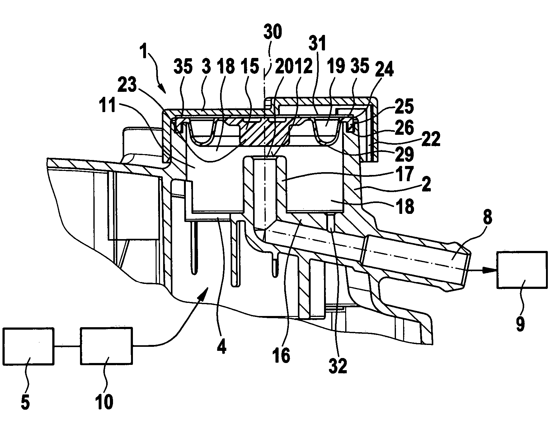
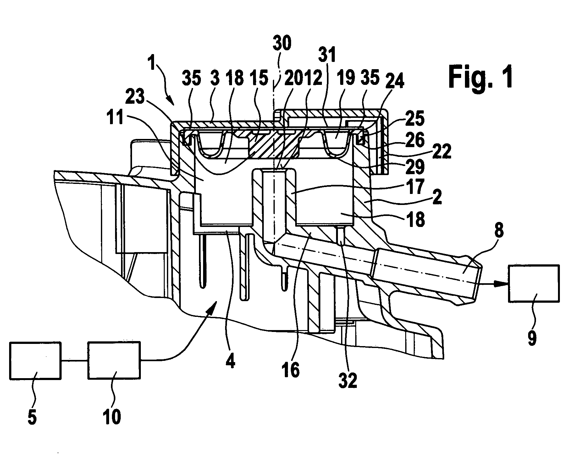
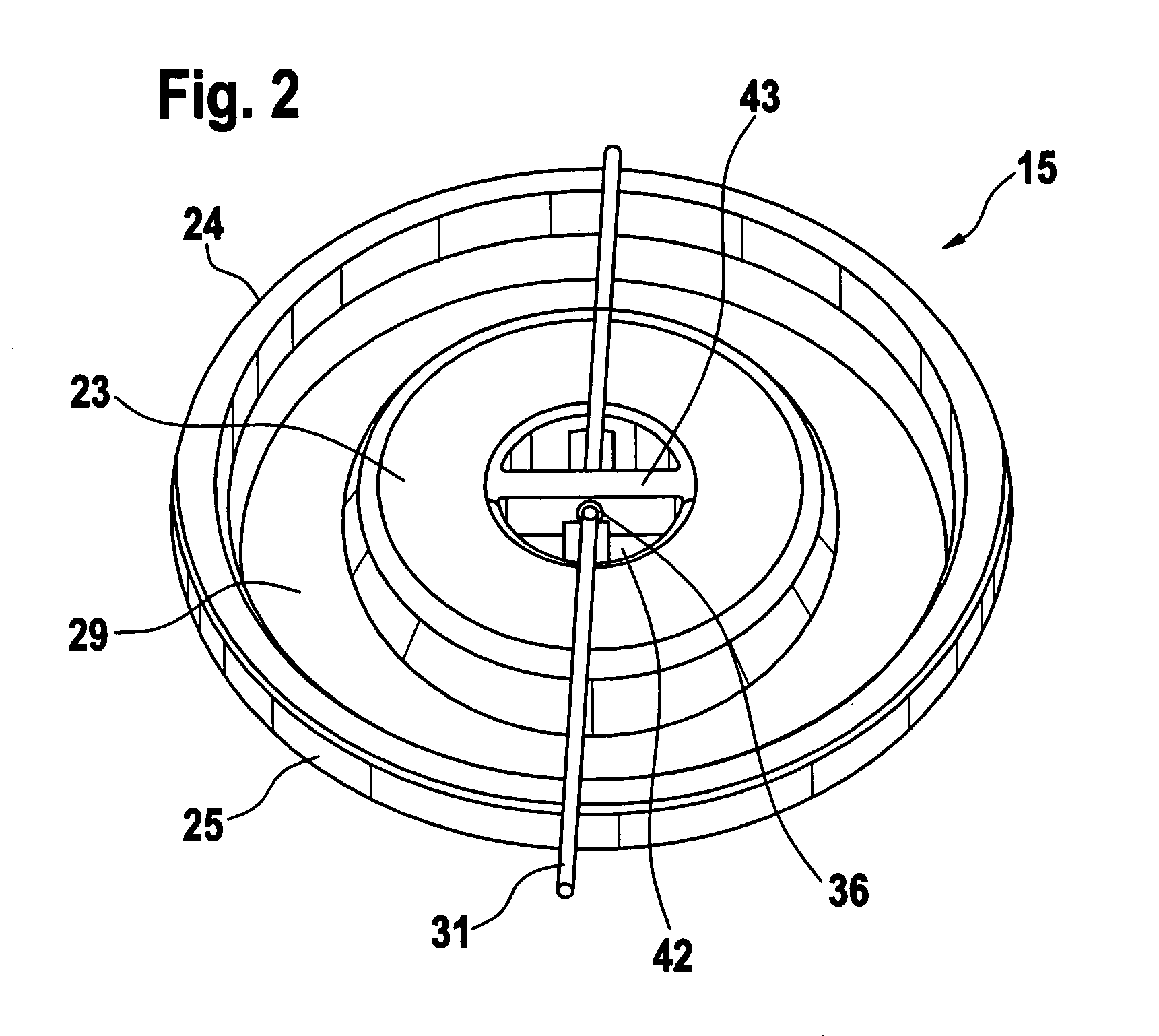
[0003] The pressure regulating valve of the invention, having the definitive characteristics of the main claim, has the advantage over the prior art that in a simple way, an improvement is attained such that the service life of the restoring spring is increased and the spring force is kept constant, because the restoring spring is embodied as a tension spring and is located on the side of the valve closing body facing away from the valve seat.
[0004] In this way, the restoring spring is no longer exposed to the aggressive gases.

Problems solved by technology

It is disadvantageous that the restoring spring is disposed in a pressure chamber, which has the valve seat and through which aggressive blowby gases flow out of the crankcase.
The blowby gases for instance have a corrosive, etching effect on the material of the restoring spring, shortening the service life and lessening the spring force of the restoring spring.
This has a highly adverse effect on the regulation of the pressure in the crankcase.

Method used


Image

  • Pressure regulating valve
  • Pressure regulating valve
  • Pressure regulating valve

Examples


Embodiment Construction

[0018]FIG. 1 shows a pressure regulating valve of the invention.

[0019] The pressure regulating valve of the invention is preferably employed in a crankcase venting system, for regulating a pressure in a crankcase to a constant value that is predetermined by the spring force of a restoring spring. However, it is also expressly possible for the pressure regulating valve to be used in other areas for pressure regulation.

[0020] During operation of an internal combustion engine, so-called blowby gas flows out of a combustion chamber into a crankcase, because of a slight leakage between the piston, piston rings, and cylinder running faces. For this blowby gas, the general term “gas” will also simply be used. Because of the slight leakage of gas from the combustion chamber of the engine, an impermissible increase in pressure occurs in the crankcase, making it necessary to achieve a pressure equilibrium by so-called crankcase venting. Since the gas has a high hydrocarbon concentration, th...


PUM


Abstract

Known pressure regulating valves have a valve closing body, which cooperates with a valve seat, and a restoring spring, which acts on a valve closing body in the direction facing away from the valve seat. It is disadvantageous that the restoring spring is disposed in a pressure chamber, which has the valve seat and through which aggressive blowby gases flow out of the crankcase. The blowby gases for instance have a corrosive, etching effect on the material of the restoring spring, shortening the service life and lessening the spring force of the restoring spring. This has a highly adverse effect on the regulation of the pressure in the crankcase. In the pressure regulating valve of the invention, the service life of the restoring spring is increased. According to the invention, the restoring spring (31) is embodied as a tension spring and is located on the side of the valve closing body (15) facing away from the valve seat (12).

Description

BACKGROUND OF THE INVENTION [0001] The invention is based on a pressure regulating valve. [0002] A pressure regulating valve is already known from German Patent DE 195 07 202 C2, having a valve closing body, which cooperates with a valve seat, and a restoring spring, which acts on a valve closing body in the direction facing away from the valve seat. It is disadvantageous that the restoring spring is disposed in a pressure chamber, which has the valve seat and through which aggressive blowby gases flow out of the crankcase. The blowby gases for instance have a corrosive, etching effect on the material of the restoring spring, shortening the service life and lessening the spring force of the restoring spring. This has a highly adverse effect on the regulation of the pressure in the crankcase. SUMMARY OF THE INVENTION [0003] The pressure regulating valve of the invention, having the definitive characteristics of the main claim, has the advantage over the prior art that in a simple way...

Claims


Application Information

Patent Timeline
IPC IPC(8): F01L13/08F01M13/00F01M13/04F02M25/06F16K17/04F16K17/30G05D16/06
CPCF01M13/0011G05D16/0661F01M2013/0016Y10T137/86622
Inventor HEZEL, BRUNOCHRISTEN, MARKUSULRICH, MARKUS
Owner ROBERT BOSCH GMBH
Learn More