Hybrid bucket and related method of pocket design

Inactive Publication Date: 2005-11-10
GENERAL ELECTRIC CO
View PDF3 Cites 17 Cited by
  • Summary
  • Abstract
  • Description
  • Claims
  • Application Information

AI Technical Summary

Benefits of technology

[0009] In another aspect, the invention relates to a steam turbine rotor wheel comprising a row of blades secured about a circumferential periphery of the wheel, each blade formed with one or more

Problems solved by technology

This increasing section area of the blade at lower spans contributes to excessive flow blockage at the root and thus lower performance.
The weight of the blade also contributes to higher disk stresses and thus potentially to reduced reliability.
One area not addressed by the prior work in this area is the problem of achieving more reliable adhesion of the filler within the pocket or pockets formed in th

Method used


Image

  • Hybrid bucket and related method of pocket design
  • Hybrid bucket and related method of pocket design
  • Hybrid bucket and related method of pocket design

Examples


Embodiment Construction

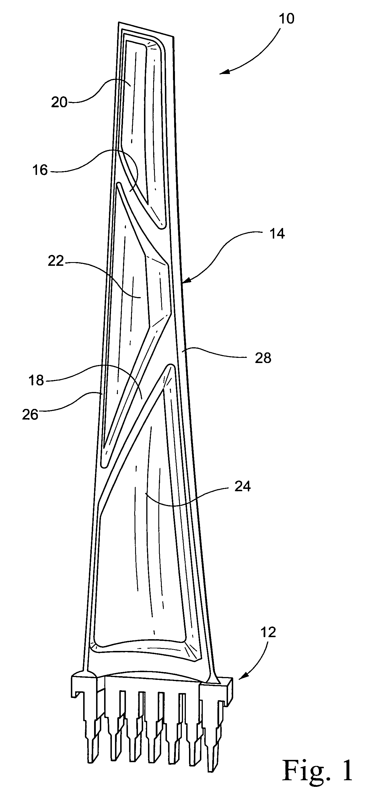
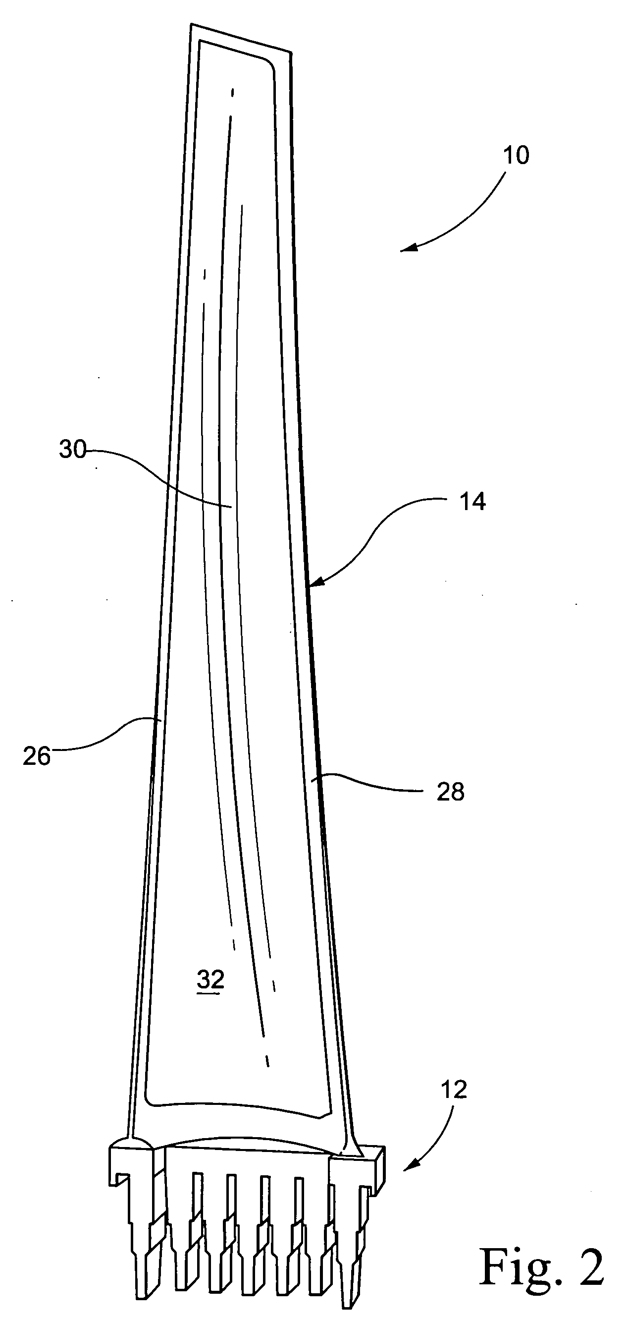
[0019] With reference to FIG. 1, a steam turbine blade 10 is shown in partially manufactured form. The blade 10 includes a shank portion 12 and an airfoil portion 14. The airfoil portion is preferably constructed of steel or titanium but other suitable materials include aluminum, cobalt or nickel. Ribs 16, 18 are integrally cast with the airfoil portion to form discrete pockets 20, 22 and 24. It will be appreciated, however, that the ribs do not extend flush with the side edges 26, 28 of the airfoil portion. The rib height may in fact vary according to specific applications. A polymer based (or polymer / metal, glass or ceramics mix) filler material 30 as described, for example, in U.S. Pat. Nos. 6,287,080 and 5,931,641 is cast-in-place over the pressure side of the airfoil, filling the pockets 20, 22 and 24 and covering the ribs to thereby form a smooth face on the pressure side of the bucket, as shown in FIG. 2.

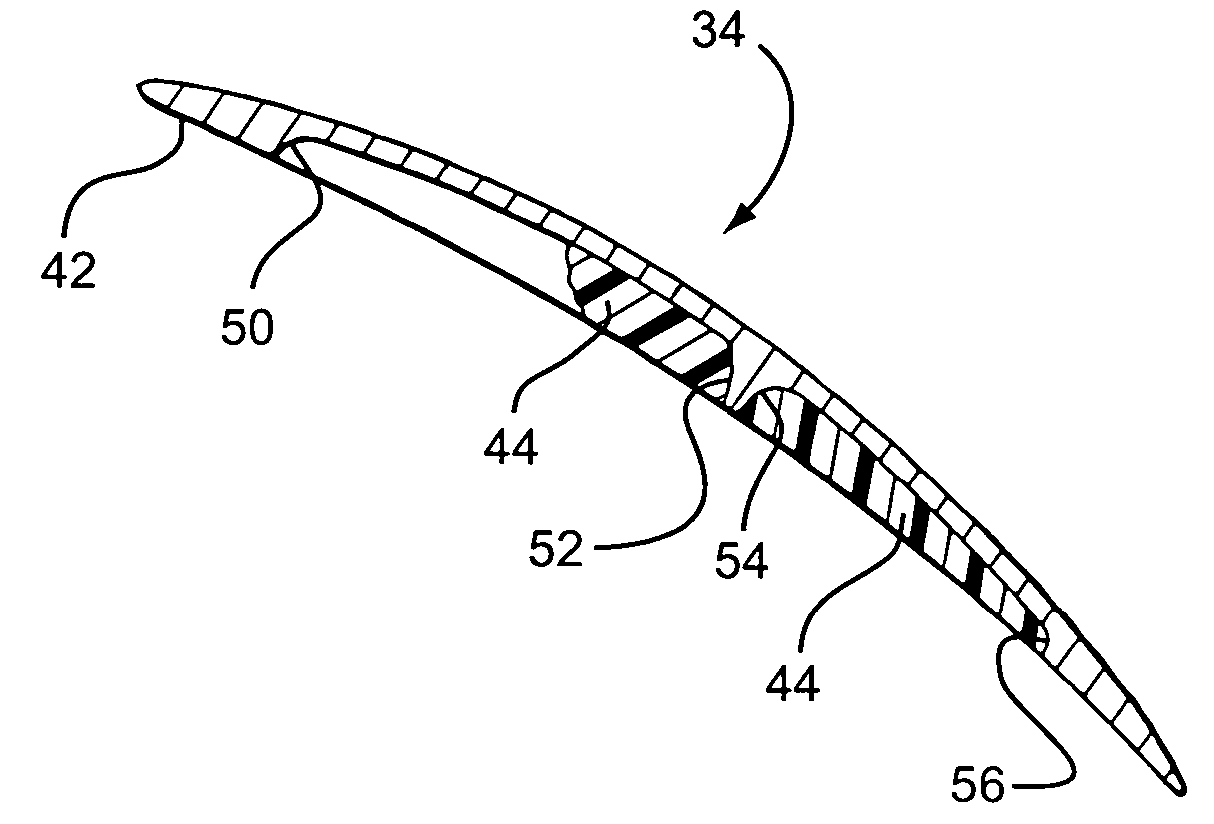
[0020]FIGS. 3 and 4 illustrate another known hybrid blade construction ...


PUM

PropertyMeasurementUnit
Pressureaaaaaaaaaa
Adhesion strengthaaaaaaaaaa

Abstract

A steam turbine rotor wheel includes a plurality of blades secured about a circumferential periphery of the wheel, each blade comprising a shank portion and an airfoil portion, the airfoil portion having at least one pocket filled with a filler material, wherein at least one edge of the pocket adjacent a leading edge of the blade is formed with an undercut.

Description

BACKGROUND OF THE INVENTION [0001] This invention relates generally to steam turbine buckets (or blades) and, more particularly, to the adhesion of filler material in hybrid or composite blades. [0002] Steam turbine blades operate in an environment where they are subject to high centrifugal loads and vibratory stresses. Vibratory stresses increase when blade natural frequencies become in resonance. The magnitude of vibratory stresses when a blade vibrates in resonance is proportional to the amount of damping present in the system (damping to a smaller or greater degree is achieved via materials and the aerodynamic and mechanical components), as well as the vibration stimulus level. [0003] At the same time, centrifugal loads are a function of the operating speed, the mass of the blade, and the radius from engine centerline where that mass is located. As the mass of the blade increases, the physical area or cross-sectional area must increase at lower radial heights to be able to carry...

Claims


Application Information

Patent Timeline
IPC IPC(8): F01D5/02F01D5/14F01D5/16F01D5/28
CPCF01D5/147F01D5/16F01D5/282F05D2220/31Y10S416/50F05D2250/29F05D2300/43F05D2300/21F05D2300/2102F05D2230/10
Inventor BURDGICK, STEVEN SEBASTIAN
Owner GENERAL ELECTRIC CO
Why Eureka
Try Eureka