Solid electrolyte fuel cell configuration

a fuel cell and solid electrolyte technology, applied in the field of solid electrolyte fuel cell configuration, can solve the problems of reduced cell configuration performance, difficulty in improving the durability of the fuel cell, and danger of explosion of mixed fuel gas, so as to reduce the size, improve the durability, and reduce the cost

Inactive Publication Date: 2005-11-10
SHINKO ELECTRIC IND CO LTD
View PDF5 Cites 45 Cited by
  • Summary
  • Abstract
  • Description
  • Claims
  • Application Information

AI Technical Summary

Benefits of technology

[0019] An object of the present invention is to provide a solid electrolyte fuel cell configuration comprised of a single sheet shaped solid electrolyte substrate formed with a plurality of fuel cells and thereby not having a sealed structure, achieving a reduction of the size and a reduction of the cost, and able to improve the durability and improve the power generation efficiency.

Problems solved by technology

Since the layers are exposed to an oxidizing atmosphere and a reducing atmosphere under a high temperature, it is difficult to improve the durability of the fuel cells.
However, even in this single chamber type fuel cell configuration, the configuration has to be driven at a high temperature of about 1000° C., so there is the danger of explosion of the mixed fuel gas.
To avoid this danger, if making the oxygen concentration a concentration lower than the ignition limit, the problem arises that carbonization of the methane or other fuel proceeds and the cell configuration performance drops.
Therefore, when driven as a fuel cell configuration, there will no longer be any ignition even if there is mixed fuel gas within the ignition limit.
Therefore, a single chamber type fuel cell configuration using sheet shaped solid electrolyte fuel cells suffers from the problems of having a bulky structure and rising in cost.
Further, at the time of operation of this single chamber type fuel cell configuration, the temperature is gradually raised until a high temperature so as to prevent cracking of the solid electrolyte fuel cells, so the time until startup is long and trouble is involved.
However, in this type of fuel cell configuration, since the anode layer is formed at the outside surface of the tubular solid electrolyte layer, the radicals in the flame cannot be supplied to the top half of the anode layer and therefore the entire surface of the anode layer formed at the outside surface of the tubular solid electrolyte layer cannot be efficiently utilized.
Accordingly, the power generation efficiency was low.
Further, since the solid electrolyte fuel cell was directly heated by the flame, it was susceptible to cracking and fracturing due to the sharp changes in temperature.
The cracked or fractured solid electrolyte fuel cell then ended up breaking apart making generation of power impossible.
Therefore, when the output current may be small, but a high electromotive force is required, the configuration ends up becoming bulky and a reduction of size or reduction of cost cannot be achieved.

Method used


Image

  • Solid electrolyte fuel cell configuration
  • Solid electrolyte fuel cell configuration
  • Solid electrolyte fuel cell configuration

Examples


first embodiment

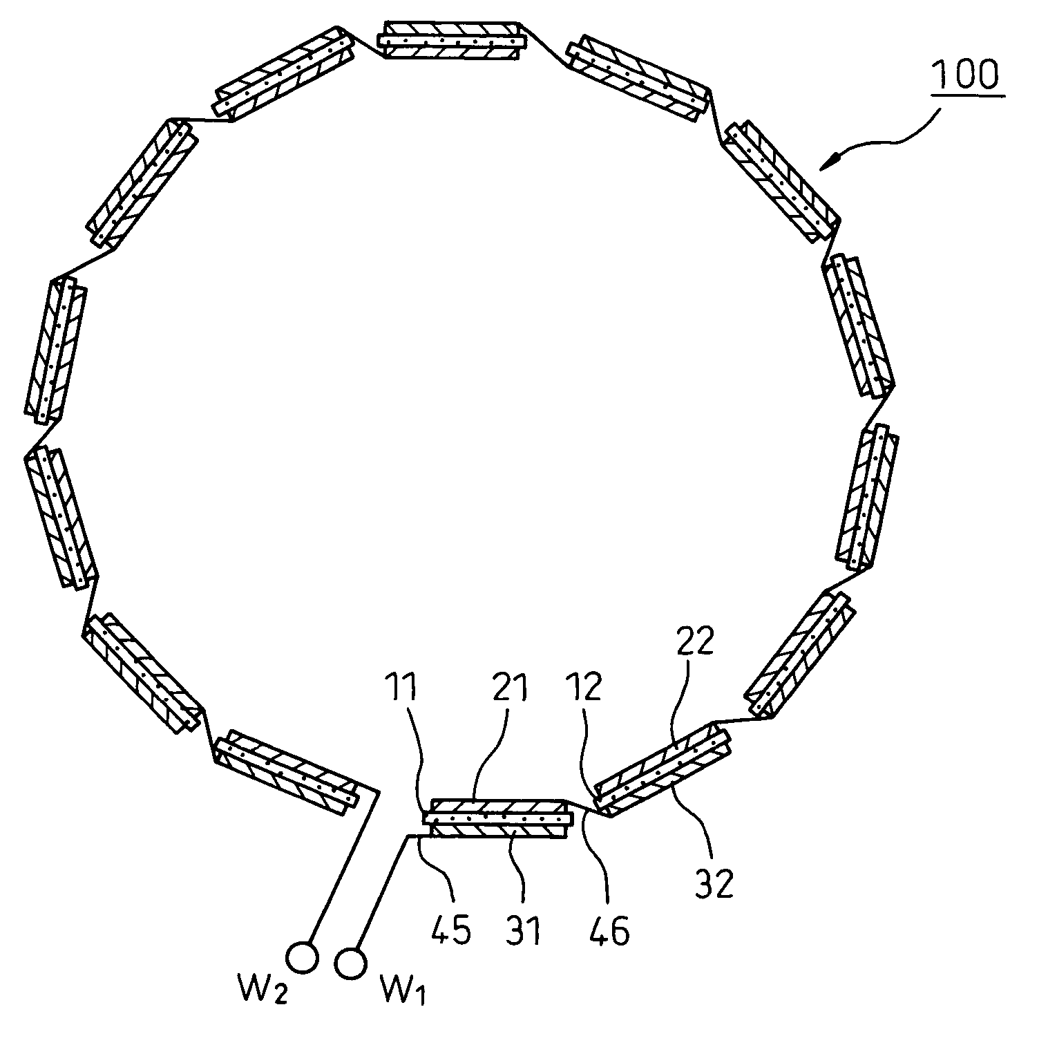
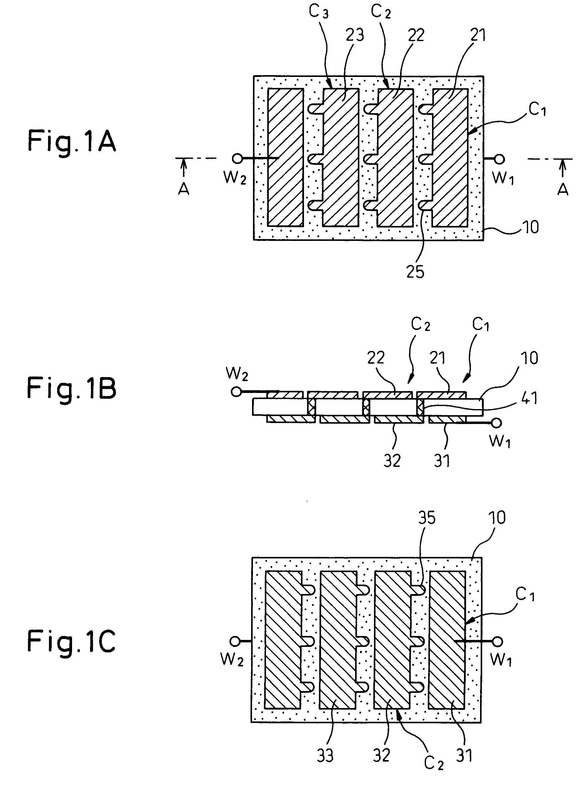
[0052]FIGS. 1A to 1C show the configuration of a solid electrolyte fuel cell configuration according to a first embodiment of the present invention. FIG. 1A is a plan view of the basic configuration viewing the solid electrolyte fuel cell configuration from an anode side, FIG. 1B is a cross-sectional view along the line A-A, and FIG. 1C is a plan view of the basic configuration viewed from a cathode side.

[0053] In the solid electrolyte fuel cell configuration making direct use of a flame according to the related art, the solid electrolyte layer was tubular in shape, so the ratio of exposure of the flame to the anode layer formed at the outside of the solid electrolyte layer was poor. Further, a single fuel cell was formed by a single tubular solid electrolyte layer. Therefore, in the solid electrolyte fuel cell configuration of the first embodiment, the solid electrolyte layer was shaped as a sheet. For example, a solid electrolyte substrate using a thin sheet was used. One surface...

second embodiment

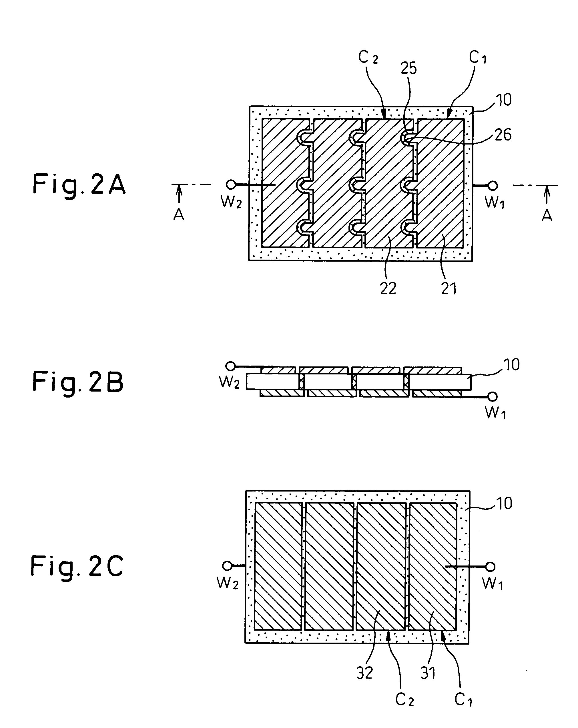
[0080]FIGS. 2A to 2C show the configuration of a solid electrolyte fuel cell configuration according to a second embodiment of the present invention. FIG. 2A is a plan view of the basic configuration viewing the solid electrolyte fuel cell configuration from an anode side, FIG. 2B is a cross-sectional view along the line A-A, and FIG. 2C is a plan view of the basic configuration viewed from a cathode side. Only the parts different from the first embodiment shown in FIGS. 1A to 1C will be explained.

[0081] In the first embodiment, both the plurality of rectangular anode layers 21, 22 . . . formed on one surface of the single solid electrolyte substrate 10 and the plurality of rectangular cathode layers 31, 32 . . . formed on the other surface have gaps between adjoining anode layers and cathode layers of at least the regions required for forming the projections 25, 35. In the second embodiment, however, the gaps between the adjoining anode layers and cathode layers are made narrower ...

third embodiment

[0087]FIGS. 3A to 3C show the configuration of a solid electrolyte fuel cell configuration according to a third embodiment of the present invention. FIG. 3A is a plan view of the basic configuration viewing the solid electrolyte fuel cell configuration from an anode side, FIG. 3B is a cross-sectional view along the line A-A, and FIG. 3C is a plan view of the basic configuration viewed from a cathode side. Only the parts different from the second embodiment shown in FIGS. 2A to 2C will be explained.

[0088] In the third embodiment, a single solid electrolyte substrate 10 is formed with a total of (4×4=) 16 fuel cells C1, C2 . . . in lattice-shaped or grid-shaped sections in the vertical direction and horizontal direction. In the first column, the anode layers of the fuel cells and the cathode layers of the adjoining fuel cells are successively serially connected straight in the same way as the above embodiments, the anode layers of the fuel cells are connected at the ends of the colum...


PUM

PropertyMeasurementUnit
drive temperatureaaaaaaaaaa
temperatureaaaaaaaaaa
porosityaaaaaaaaaa

Abstract

A solid electrolyte fuel cell configuration provided with a single sheet shaped solid electrolyte substrate formed with a plurality of fuel cells and thereby not having a sealed structure, achieving a reduction of the size and a reduction of the cost, and able to improve the durability and improve the power generation efficiency, a single sheet shaped solid electrolyte substrate, in particular a solid electrolyte fuel cell configuration provided with a single sheet shaped solid electrolyte substrate, a plurality of anode layers formed on one side of the solid electrolyte substrate, and a plurality of cathode layers formed on the side opposite to the one side of the solid electrolyte substrate at positions facing the anode layers, the anode layers and cathode layers facing each other across the solid electrolyte substrate forming a plurality of fuel cells, the anode layers and cathode layers being connected in series.

Description

BACKGROUND OF THE INVENTION [0001] 1. Field of the Invention [0002] The present invention relates to a solid electrolyte fuel cell configuration, more particularly relates to a solid electrolyte fuel cell configuration comprised of a solid electrolyte substrate formed with pluralities of anode layers and cathode layers and enabling a smaller size, greater thinness, and higher output by a simple structure not requiring sealing. [0003] 2. Description of the Related Art [0004] In the past, fuel cell configurations have been developed and put into practical use as low polluting power generating means for taking the place of thermal power generation or as sources of electrical energy for electric cars for taking the place of engines fueled by gasoline etc. Considerable research is going on for increasing the efficiency and reducing the cost of such fuel cell configurations. [0005] These fuel cell configurations generate power by various systems. Among these, there are types of fuel cell ...

Claims


Application Information

Patent Timeline
Patent Type & Authority Applications(United States)
IPC IPC(8): H01M4/86H01M8/10H01M8/12H01M8/02H01M8/24
CPCH01M8/006H01M8/0256H01M8/1097H01M8/1226H01M8/1286Y02B90/18H01M8/2465H01M2008/1293H01M2250/30Y02E60/521Y02E60/525H01M8/2425Y02B90/10Y02E60/50H01M8/2432H01M8/02H01M8/24
Inventor HORIUCHI, MICHIOSUGANUMA, SHIGEAKIWATANABE, MISATOKUTAKE, YASUE
Owner SHINKO ELECTRIC IND CO LTD
Why Eureka
Try Eureka