Thin autotensioner
- Summary
- Abstract
- Description
- Claims
- Application Information
AI Technical Summary
Benefits of technology
Problems solved by technology
Method used
Image

Examples
first embodiment
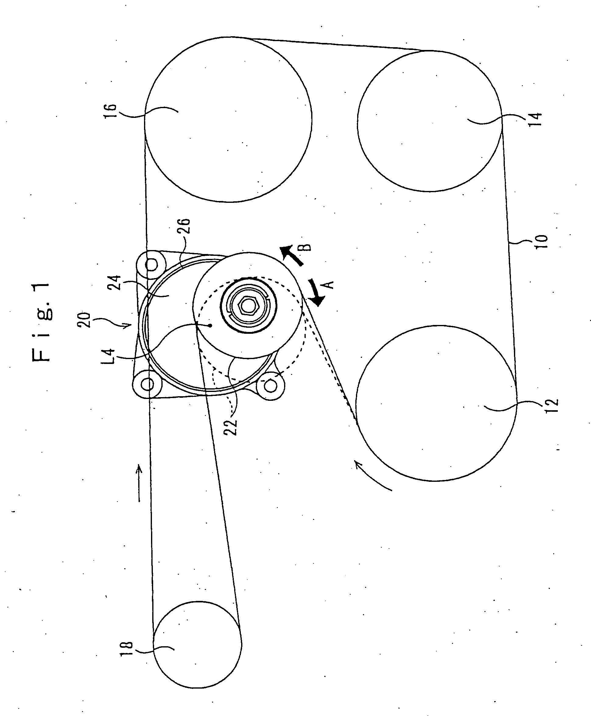
[0056]FIG. 1 is a view of a belt drive mechanism employing an autotensioner according to the present invention. The belt drive mechanism has a single endless belt 10. This belt 10 is wrapped around a drive pulley 12 attached to an output shaft of an engine (not shown), and driven pulleys attached to a plurality of apparatuses, for example, an air-conditioner pulley 14, a power steering system pulley 16, and an alternator pulley 18. When the drive pulley 12 rotates, the belt 10 rotates in the clockwise direction of the drawing and the rotational drive force is transmitted to the pulleys 14, 16, and 18 of the equipment.
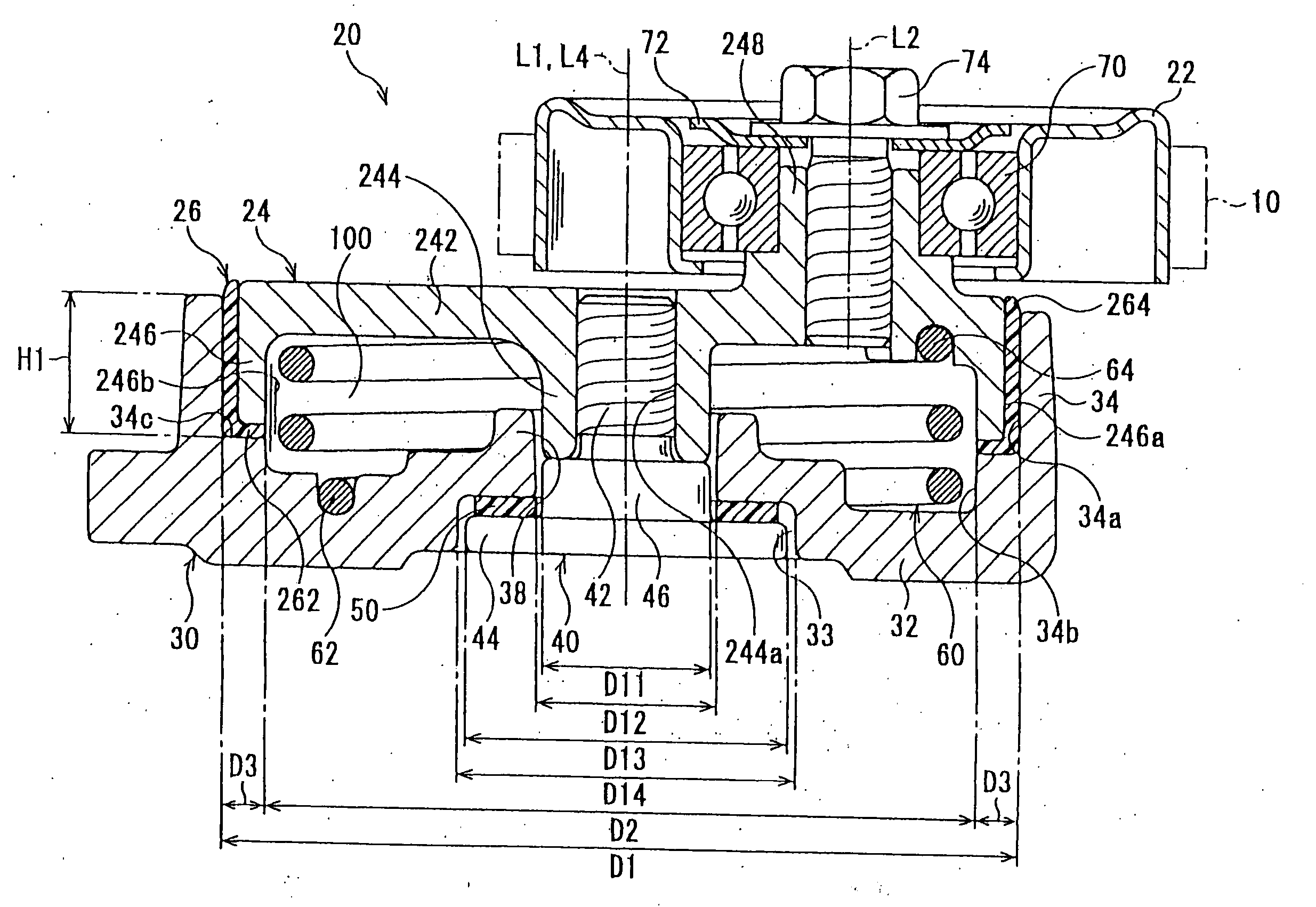
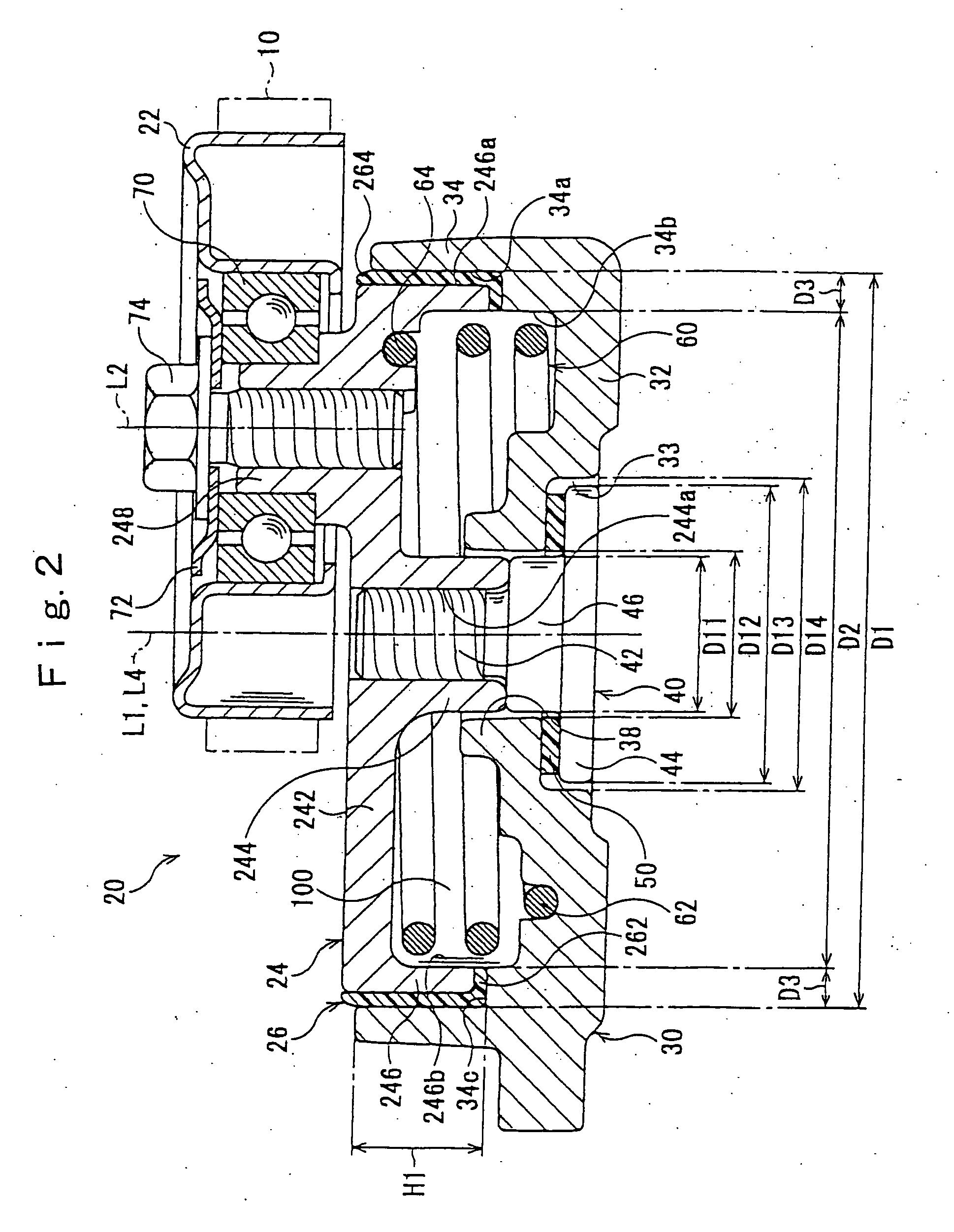
[0057] The autotensioner 20 is arranged in proximity to the drive pulley 12, more particularly in the belt rotational direction after the drive pulley 12 where the belt 10 most easily becomes slack. The pulley 22 of the autotensioner 20 abuts against the back surface of the belt 10. Namely, the pulley 22 contacts the outer circumference side of the belt, while the pulle...
second embodiment
[0112] The bushing 426 of the second embodiment is a semitubular member provided extending over a range of 180 degrees around the base axial center L1. The center in the circumferential direction is on the axial load direction Y. Namely, the bushing 426 slides against the arm outer circumferential surface 246a across a range of ±90 degrees from the axial load direction Y.
[0113] The bushing 26 in the first embodiment is a tubular shape, and the portion most receiving the load is the pushing position 26w in the axial load direction Y (FIG. 4). This receives the load for exactly the range of about ±90 degrees from the axial load direction Y. Therefore, at the position at the opposite side, the bushing 26 is separated from the arm outer circumferential surface 246a, and no frictional force is generated. Due to this, in the second embodiment, the semitubular portion extending over the range of ±90 degrees from the axial load direction Y required for the frictional sliding is used as the ...
fourth embodiment
[0118] In the autotensioner 620 of the fourth embodiment, a ring-shaped chamber 700 is formed by the base bottom 632, the arm disk 842, the bottom inner circumferential surface 634b of the base 630, the arm inner circumferential surface 846b, the base shaft hole part 638, and the rocking shaft 844. The ring-shaped chamber 700 houses not only the torsion coil spring 660, but also the damping mechanism.
[0119] In the first embodiment, the only member imparting frictional resistance to the rocking arm 24 is the bushing 26, and sometimes a sufficient damping force may not be obtained with just the bushing 26. The fourth embodiment is further provided with a separate damping mechanism imparting a frictional force to the rocking arm 624 to meet with this demand, so that a high damping force is generated.
[0120] The damping mechanism is provided with a second tubular part 702 integral with the base 30, a tubular damping member 704 attached to the rocking arm 624, and a ring spring 706 pushi...
PUM
| Property | Measurement | Unit |
|---|---|---|
| Angle | aaaaa | aaaaa |
| Length | aaaaa | aaaaa |
| Force | aaaaa | aaaaa |
Abstract
Description
Claims
Application Information
 - R&D Engineer
- R&D Manager
- IP Professional
- Industry Leading Data Capabilities
- Powerful AI technology
- Patent DNA Extraction
Browse by: Latest US Patents, China's latest patents, Technical Efficacy Thesaurus, Application Domain, Technology Topic.
© 2024 PatSnap. All rights reserved.Legal|Privacy policy|Modern Slavery Act Transparency Statement|Sitemap