Conductive polymeric structures containing graphite nanofibers having graphite sheets parallel to the growth axis

a technology of graphite nanofibers and conductive polymers, which is applied in the direction of non-conductive materials with dispersed conductive materials, special tyres, transportation and packaging, etc., can solve the problems of difficult extrusion and draw into fibers of conventional conductive fillers such as carbon black, metal or metal oxide powders, and significantly lower electrical conductivity in those regions

Inactive Publication Date: 2005-11-10
CATALYTIC MATERIALS
View PDF10 Cites 22 Cited by
  • Summary
  • Abstract
  • Description
  • Claims
  • Application Information

AI Technical Summary

Benefits of technology

[0010] In accordance with the present invention there is provided a polymer composite comprised of a polymer matrix and an effective amount of substantially crystalline graphitic nanofibers consisting essentially of substantially graphite discontinuous sheets that are substantially parallel to the longitudinal axis of the nanofiber, wherein the distance

Problems solved by technology

Thermoplastics such as nylons, polyethylenes, polypropylenes, polyvinylchlorides and polyesters that contain conventional particulate conductive fillers such as carbon black, metal or metal oxide powders are difficult to extrude and draw into a fiber.
Such a material, however, suffers from the fact that while the bulk properties of the polymer exhibit high electrical conductivity, the poor contact of the conductive component with th

Method used


Image

  • Conductive polymeric structures containing graphite nanofibers having graphite sheets parallel to the growth axis
  • Conductive polymeric structures containing graphite nanofibers having graphite sheets parallel to the growth axis
  • Conductive polymeric structures containing graphite nanofibers having graphite sheets parallel to the growth axis

Examples


example 1

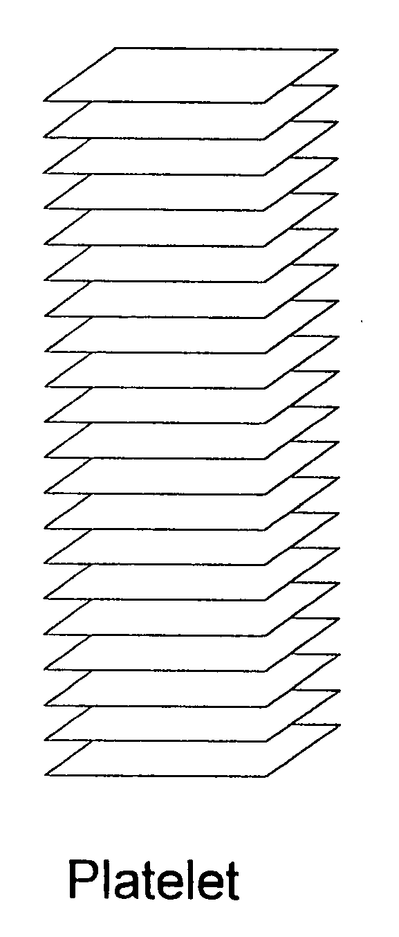
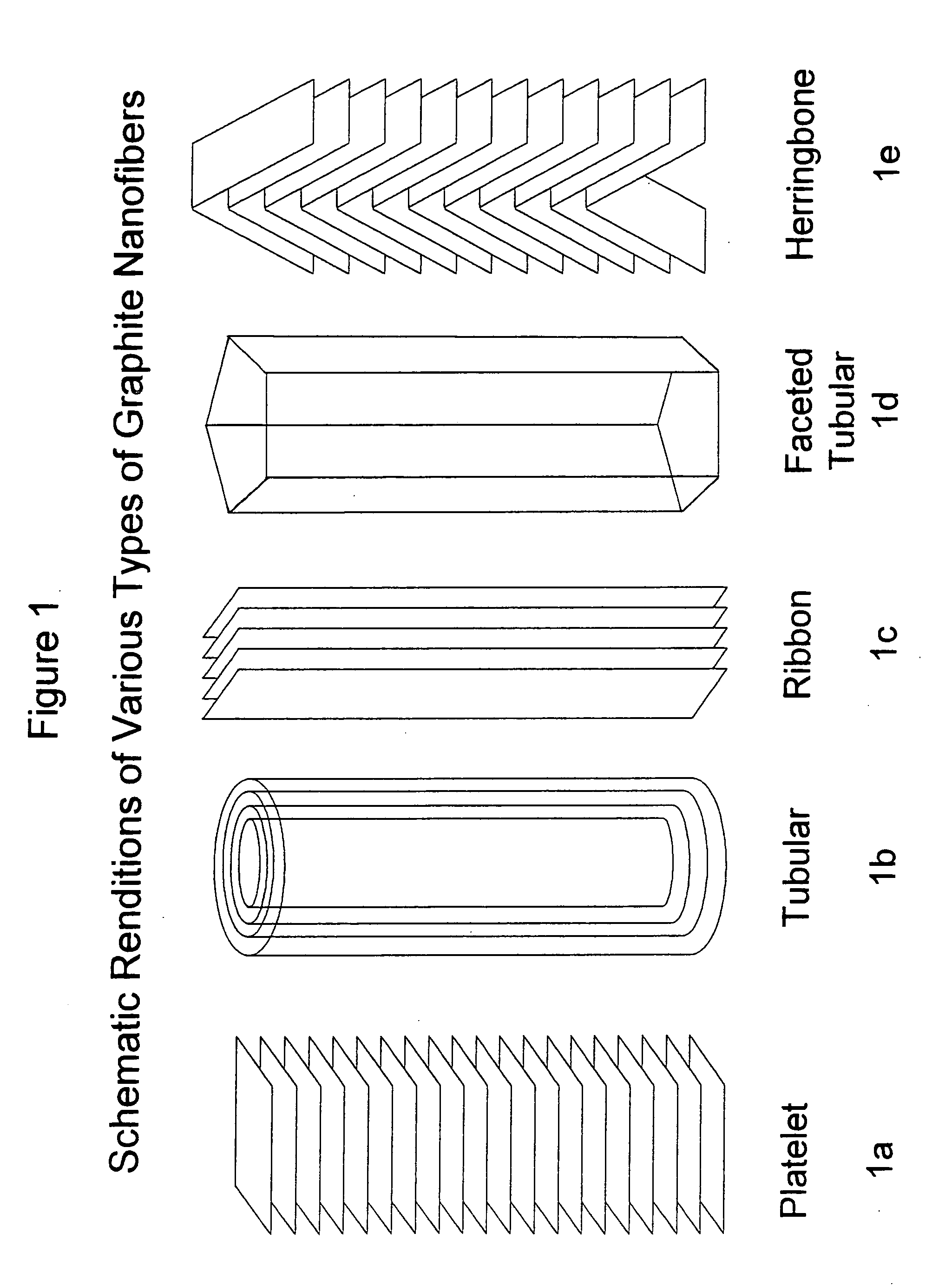
[0036] A powered bimetallic catalyst comprised of Fe—Ni (6:4) was reacted in CO / H2 at various temperatures shown in Table I below ranging from 450° C. to 750° C. The resulting graphite nanofibers showed distinct differences in their structural characteristics. The graphite nanofibers generated at temperatures from about 625° C. to 725° C. were found to be comprised of a structure in which the graphite sheets were aligned in direction substantially parallel to the longitudinal fiber axis and adopted a multi-faceted cross-sectional geometry. As the temperature was raised to 750° C. the tendency for graphite shells to be formed increased.

TABLE ITemperature (° C.)Characteristics of Solid Carbon Product400A few spiral nanofibers having a “herring-bone”structure450A few spiral nanofibers having a “herring-bone”structure500Some bi-directional spiral nanofibers having a“herring-bone” structure550Some bi-directional spiral nanofibers having a“herring-bone” structure600Mixture of spiral nan...

example 2

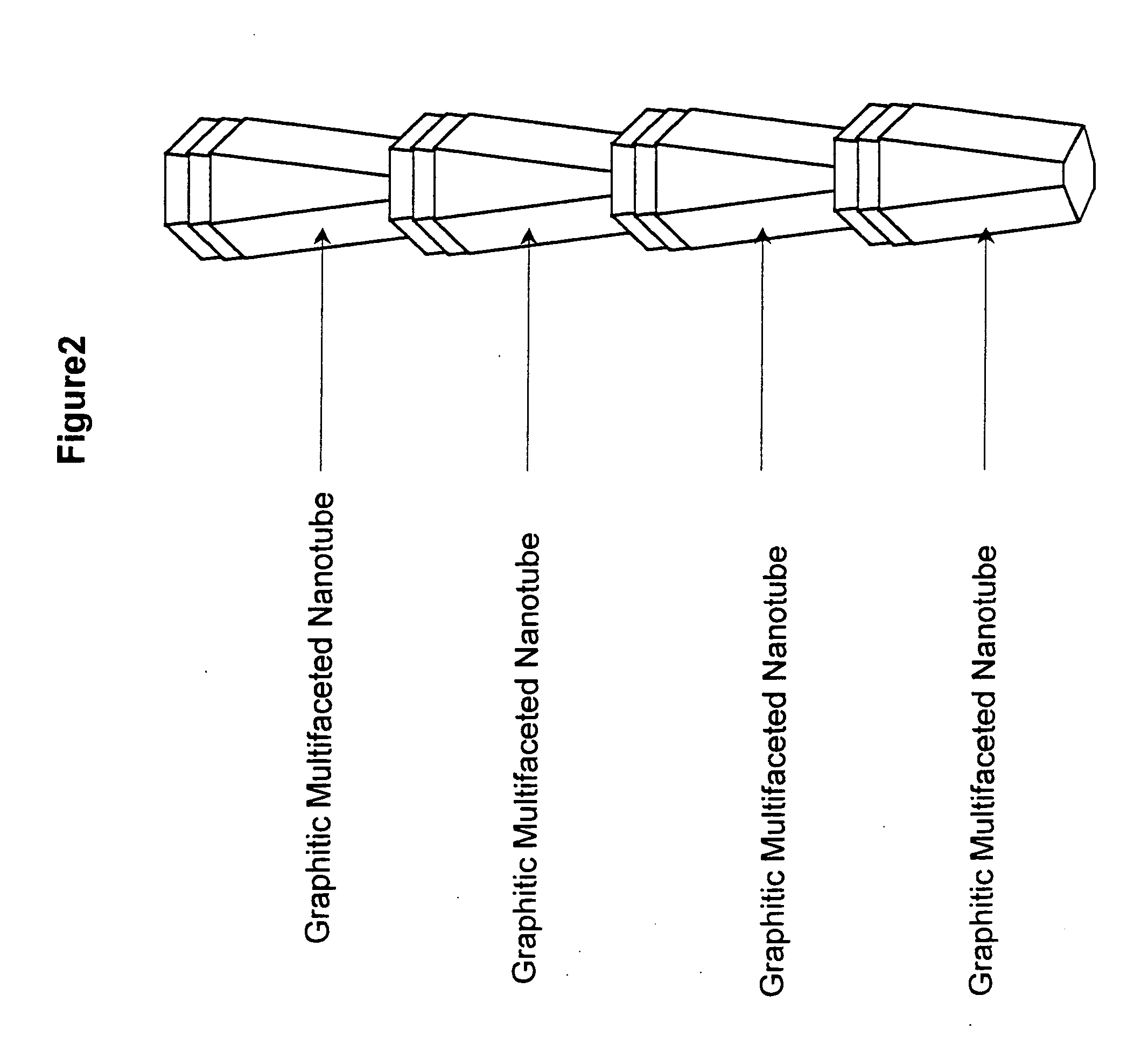
Comparison of the Chemical and Physical Properties of Multi-Faceted Multi-Walled Nanotubes (MWNT) and Cylindrical MWNT

[0037] A series of experiments was carried out to compare the chemical and physical properties of cylindrical MWNT and multi-faceted MWNT. Table II below shows the results of these experiments.

TABLE IIMulti-facetedMWNTCylindrical MWNTSurface Area (m2 / g)178297Average Width (nm)11.618d002 XRD (nm)0.3360.354Conductivity (Ω.cm)7.7 × 10−23.2 × 10−2Onset CO2 Reactivity (° C.)650860

[0038] Inspection of these data evidences the existence of substantial differences between these two types of MWNT. It is quite probable that the variation in surface areas is merely a reflection of the difference in the relative widths of the two structures, with the cylindrical MWNT being the smaller, since they are generated from a supported metal catalyst rather than a bimetallic powder.

[0039] There is a 5% difference in the spacing of adjacent graphite layers with multi-faceted MWNT bein...

example 3

[0041] In this set of experiments, various amounts of the two types of carbon nanotubes were ultrasonically mixed with polymethyl methacrylate (PMMA) to produce thin composite films. The electrical surface resistivity of the resulting polymer / carbon nanotube films was determined at room temperature on similar thickness samples 1 cm×1 cm. Examination of the data presented in Table XII below shows that the polymer samples containing dispersed multi-faceted MWNT of the present invention had a resistance of about two orders of a magnitude less than the corresponding samples containing conventional cylindrical MWNT.

TABLE IIINanotube LoadingCylindrical MWNTMulti-faceted MWNT(wt. %)(Ohms / sq)(Ohms / sq)2.06.7 × 1067.0 × 1044.01.5 × 1056.0 × 1038.03.6 × 1049.6 × 102


PUM

PropertyMeasurementUnit
Fractionaaaaaaaaaa
Distanceaaaaaaaaaa
Distanceaaaaaaaaaa

Abstract

Electrically conductive polymer composite materials comprised of: a) an effective amount of substantially crystalline graphitic carbon nanofibers comprised of graphite sheets that are substantially parallel to the longitudinal axis of the nanofiber, preferably wherein said grip sheets form a multifaceted tubular structure; and b) a polymeric component.

Description

CROSS-REFERENCE TO RELATED APPLICATIONS [0001] This application is a continuation-in-part of U.S. Ser. No. 10 / 969,129, which was filed on Oct. 18, 2004, which was a continuation-in-part of U.S. Ser. No. 09 / 902,113 filed Jul. 10, 2001, which is a continuation-in-part of U.S. Ser. No. 09 / 659,441 filed Sep. 8, 2000. This is also a continuation-in-part of U.S. Ser. No. 10 / 015,353 filed Dec. 11, 2001.FIELD OF THE INVENTION [0002] This invention relates to electrically conductive polymer composite materials comprised of: a) an effective amount of substantially crystalline graphitic carbon nanofibers comprised of graphite sheets that are substantially parallel to the longitudinal axis of the nanofiber, preferably wherein said graphite sheets form a multifaceted tubular structure; and b) a polymeric component. DESCRIPTION OF RELATED ART [0003] It is well established that the incorporation of certain types of carbon nanofibers into polymeric materials can impart electrical conductivity to su...

Claims


Application Information

Patent Timeline
IPC IPC(8): C08K3/04C08K7/06
CPCB82Y30/00C08J5/005H01B1/24C08K2201/011C08K7/06Y10S977/778
Inventor BAKER, R. TERRY K.RODRIGUEZ, NELLY M.
Owner CATALYTIC MATERIALS
Why Eureka
Try Eureka