Sensor fault diagnostics and prognostics using component model and time scale orthogonal expansions

a technology of component model and time scale, applied in the direction of programme control, instruments, total factory control, etc., can solve the problems of system cost-prohibition, system that uses redundant sensors, hvac system will not operate as intended, premature failure, etc., to achieve reliable and economical sensor fault diagnostic and prognostic technique, the effect of reliable and economical

Inactive Publication Date: 2005-11-10
CARRIER CORP
View PDF9 Cites 64 Cited by
  • Summary
  • Abstract
  • Description
  • Claims
  • Application Information

AI Technical Summary

Benefits of technology

[0011] This system provides an effective and economical sensor fault diagnostic and prognostic technique. This technique is particularly useful for dealing with the slowly occurring sensor faults such as drift and bias in sensor readings. Component models of the air handling system are used as a basis for sensor bias detection and estimation. The combination of the two-fault detection approaches, that being the comparison to component models, and the sensor and data manipulation using statistical techniques, provides a reliable method for evaluating sensor condition.
[0012] Accordingly, the method and system of this invention provides a reliable and economical method of determining sensor condition that is adaptable to current systems.

Problems solved by technology

If the sensors fail or are inaccurate, the HVAC system will not operate as intended.
Further, if the sensors fail to provide accurate data, the components within the HVAC system may operate outside desirable parameters, potentially causing premature failure.
Systems that use redundant sensors are cost-prohibitive.
Further, redundant sensors double the programming requirements and controller requirements, increasing the overall complexity of the system.
Disadvantageously, this approach can only detect complete sensor failure.
Sensor drift or bias where the sensor provides inaccurate information cannot be detected by such a system.
This data-driven approach requires a large amount of linearly related data and a statistical analysis that is complicated and computationally intensive.
The large amounts of computation can lead to inaccuracies and increased costs.

Method used


Image

  • Sensor fault diagnostics and prognostics using component model and time scale orthogonal expansions
  • Sensor fault diagnostics and prognostics using component model and time scale orthogonal expansions
  • Sensor fault diagnostics and prognostics using component model and time scale orthogonal expansions

Examples


Embodiment Construction

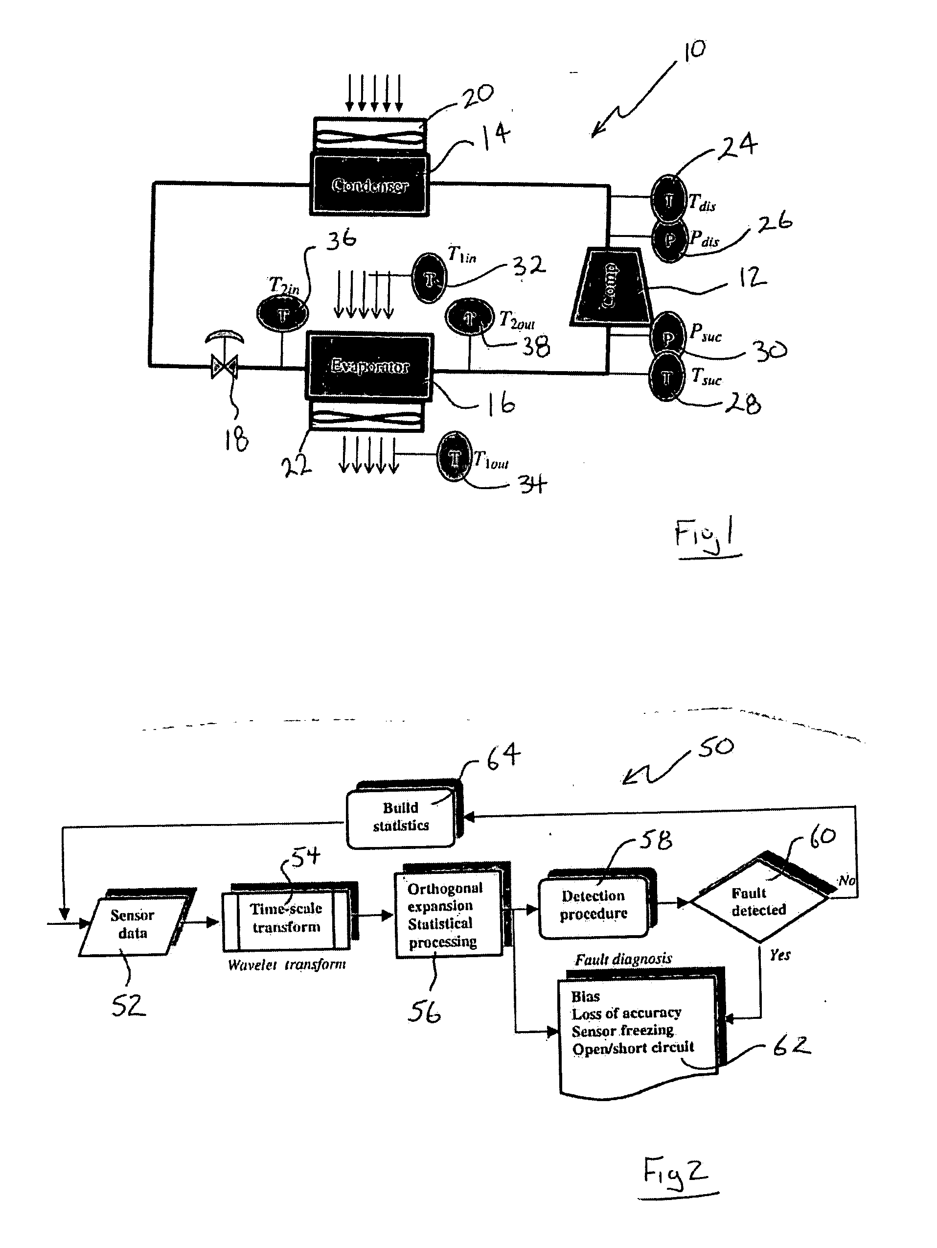
[0017] Referring to FIG. 1, a heat pump system 10 is illustrated and includes a condenser 14, a compressor 12 and an evaporator 16. An expansion valve 18 controls refrigerant flow between the evaporator 16 and the condenser 14. The compressor 12 drives refrigerant to the condenser 14. There are various sensors disposed within the system to measure temperature and pressure of refrigerant, and temperature of air moving in and out of the heat pump system 10. The compressor 12 includes a temperature sensor 24 and pressure sensor 26 that measure the temperature and pressure exiting the compressor 12. On the suction side or inlet side of the compressor 12 is a pressure sensor 30 and a temperature sensor 28.

[0018] The evaporator 16 includes temperature sensors 32, 34 that measure inlet and outlet air moving across the evaporator 16. Further, temperature sensors 36, 38 measure refrigerant temperature moving into and out of the evaporator 16.

[0019] The pressure and temperature of refrigera...


PUM


Abstract

A method of diagnosing sensor faults for a heating, ventilation and air conditioning system includes the steps of creating a component model for a specific component within the system. The component model is created through the use of commonly available manufacturing data. Data within the system is input into the component model and compared to calculated and predicted values that are also calculated using the identical component models. Differences between the calculated and actual values is determined and compared to a threshold difference value. If the difference exceeds the threshold value, then a fault is detected. The specific type of sensor fault is determined using probability distribution analysis. Each type of sensor fault produces a different type of statistical deviation from normal distribution. By recognizing these patterns of deviations from the normal distribution, the specific type of fault such as electrical, intermittent or freezing of the sensor can be determined to provide initial information as to the severity and type of remedial action required.

Description

BACKGROUND OF THE INVENTION [0001] This invention relates to temperature and pressure sensor fault detection for a heating, ventilation and air conditioning system. [0002] Typically, a heating, ventilation and air conditioning (HVAC) system includes temperature and pressure sensors that are crucial to ensure proper operation of the system. A controller uses data from the sensors to adjust operation of the components such as an evaporator, compressor and condenser. If the sensors fail or are inaccurate, the HVAC system will not operate as intended. Further, if the sensors fail to provide accurate data, the components within the HVAC system may operate outside desirable parameters, potentially causing premature failure. For these reasons, it is desirable to monitor sensor accuracy and indicate a fault condition when sensor accuracy is outside a desired operating range. [0003] Prior art sensor fault detection techniques include the use of redundant sensors to measure the same parameter...

Claims


Application Information

Patent Timeline
Patent Type & Authority Applications(United States)
IPC IPC(8): G05B9/02G06F11/30
CPCG05B2219/31359G05B9/02Y02P90/02
Inventor KANG, PENGJUFARZAD, MOHSENSTRICEVIC, SLAVENSADEGH, PAYMANFINN, ALAN M.
Owner CARRIER CORP
Why Eureka
Try Eureka