Fracture-inducing lid for isolation pocket form

a technology of fracture-inducing lids and isolation pockets, which is applied in the direction of struts, constructions, building components, etc., can solve the problems of difficult removal of temporary wooden forms, difficult to remove temporary wooden forms, and less useful floor surfaces for new “tilt-up” construction techniques, etc., to achieve save considerable time and labor, and the effect of convenient and clean breakou

Inactive Publication Date: 2005-11-17
GUILLEBEAU OTIS
View PDF19 Cites 6 Cited by
  • Summary
  • Abstract
  • Description
  • Claims
  • Application Information

AI Technical Summary

Benefits of technology

[0009] An object of this invention is to provide a lid for an isolation pocket form that enables a contractor to form a temporary 2″ concrete cover over the isolation pocket to make the slab surface smooth and continuous so that it can be used as a uniform casting bed.
[0010] Another object is to produce fracturing-inducing grooves in a concrete floor around the periphery of the isolation pocket form so that the temporary concrete cover can be easily and cleanly broken out, permitting removal of the form lid and subsequent placement of the support column on the footing.
[0011] The form lid according to this invention has a substantial perip...

Problems solved by technology

This made such floors less useful for new “tilt-up” construction techniques in which wall slabs are cast right on the floor surface.
There were numerous problems with this prior method.
First, removing the 2″ concrete cover requires one to accurately locate and cut out the exact shape and position of the actual isolation pocket.
Cutting out the cover this way is expensive and dangerous.
Thirdly, removal of the temporary wooden forms is difficult because the forms are confined, and have been in the ground long enough to have been swollen by soil moisture.
Removal of styrofoam causes problems as well, because oncrete and styrofoam foam a tenacious bond.
Gasoline and styro...

Method used


Image

  • Fracture-inducing lid for isolation pocket form
  • Fracture-inducing lid for isolation pocket form
  • Fracture-inducing lid for isolation pocket form

Examples


Embodiment Construction

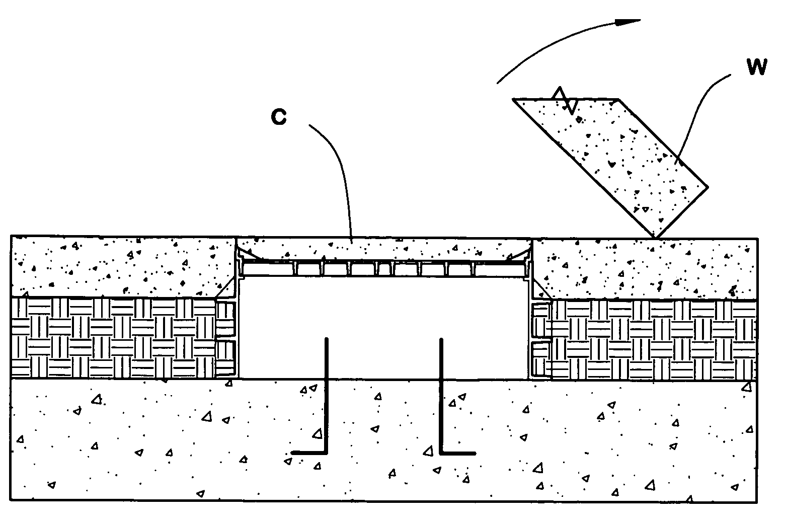
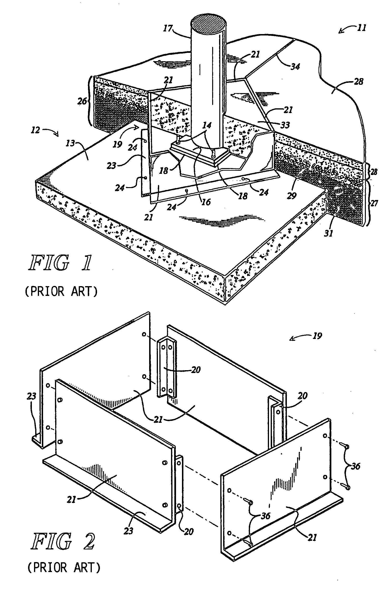
[0017] The floor structure 11 shown in FIG. 1 includes a generally rectangular concrete footing 12 that is formed with an upper load bearing surface 13. A set of anchor bolts 14 (only two of which are exposed in FIG. 1) are embedded within and extend upwardly from the upper surface 13 of the footing 12. The anchor bolts 14 provide means for securing the base plate 16 of a vertical support column 17 to the footing 12 using threaded nuts.

[0018] A generally rectangular open top form 19 is defined by four side panels 21 joined together at their ends. Each of the side panels 21 has a lower flange 23 that extends outwardly from the side panel along its bottom edge. The form 19 is mounted atop the footing 12 surrounding and isolating the base of support column 17 and is secured in place by means of concrete nails or other suitable fasteners 24 driven through the flanges 23 and into the concrete material of the footing 12. The form 19 is constructed from four similar side panels 21, and ea...


PUM


Abstract

An isolation pocket form is placed on around a footing for a support column, and then covered with a lid which has a sharp peripheral rim extending upwardly. Concrete is then poured around and over the form and lid, forming an initially continuous concrete floor which can be used as a casting bed for making wall slabs. The sharp-bottomed grooves produced in the concrete by the rim are preferential fracture sites, so that, after the wall slabs have been removed, the concrete portion overlying the isolation pocket can easily and cleanly be broken out.

Description

[0001] This application is a continuation-in-part of application Ser. No. 10 / 235,836, filed Sep. 6, 2002.BACKGROUND OF THE INVENTION [0002] This invention relates generally to the construction of large buildings of the type in which the structure of the building is supported atop vertical columns embedded in and extending upwardly from a concrete floor slab. More specifically, the invention relates to methods of creating isolation pockets about the bases of such support columns as the surrounding subgrade and concrete floor is formed to allow for adjustment of the columns and concrete encasement of the column bases. [0003] Many large buildings, such as warehouses, shopping malls, and the like, are constructed with a super-structure that is supported at predetermined intervals atop vertical columns that are embedded at their bases within and extend upwardly from the concrete floor slab of the building. When constructing such buildings, concrete footings are generally cast in the grou...

Claims


Application Information

Patent Timeline
IPC IPC(8): E02D27/42E04B5/32E04C3/32
CPCE02D27/42E04C3/32E04B5/32
Inventor GUILLEBEAU, OTIS
Owner GUILLEBEAU OTIS
Why Eureka
Try Eureka