Micromixer

a micro-mixer and mixer technology, applied in the direction of ion-exchangers, separation processes, transportation and packaging, etc., can solve the problems of inability to provide versatile, passive, non-electroosmotic mixing devices, prior art devices fail to address, etc., to achieve high degree of mixing, small internal volume, and effective mixing

Inactive Publication Date: 2005-11-17
EKSIGENT TECH
View PDF9 Cites 44 Cited by
  • Summary
  • Abstract
  • Description
  • Claims
  • Application Information

AI Technical Summary

Benefits of technology

[0008] The present invention is defined by the following claims, and nothing in this section should be taken as a limitation on those claims. Disclosed herein are methods and apparatus in capillary, microfluidic chip and larger conduit formats that provide effective mixing over a broad range of volumetric flow rates. The invention provides for devices and methods that achieve a high degree of mixing, have small internal volumes, short flow delay times and small blurring time. When combined with a pumping system suitable for direct pumping at the requisite flow rate, the devices and methods of the present invention allow fast chromatographic gradient generation. The short flow delay time provides for a substantial increase in gradient generation rate and thus provide for substantial increases in analytical sample throughput.

Problems solved by technology

These prior art devices fail to address the problem of providing versatile, passive, non-electroosmotic mixing devices and associated methods capable of operating over a wide variety of flow rates and fluid compositions, without introducing unnecessary axial dispersion.

Method used


Image

  • Micromixer
  • Micromixer
  • Micromixer

Examples


example 1

Low-Flow Rate Mixer

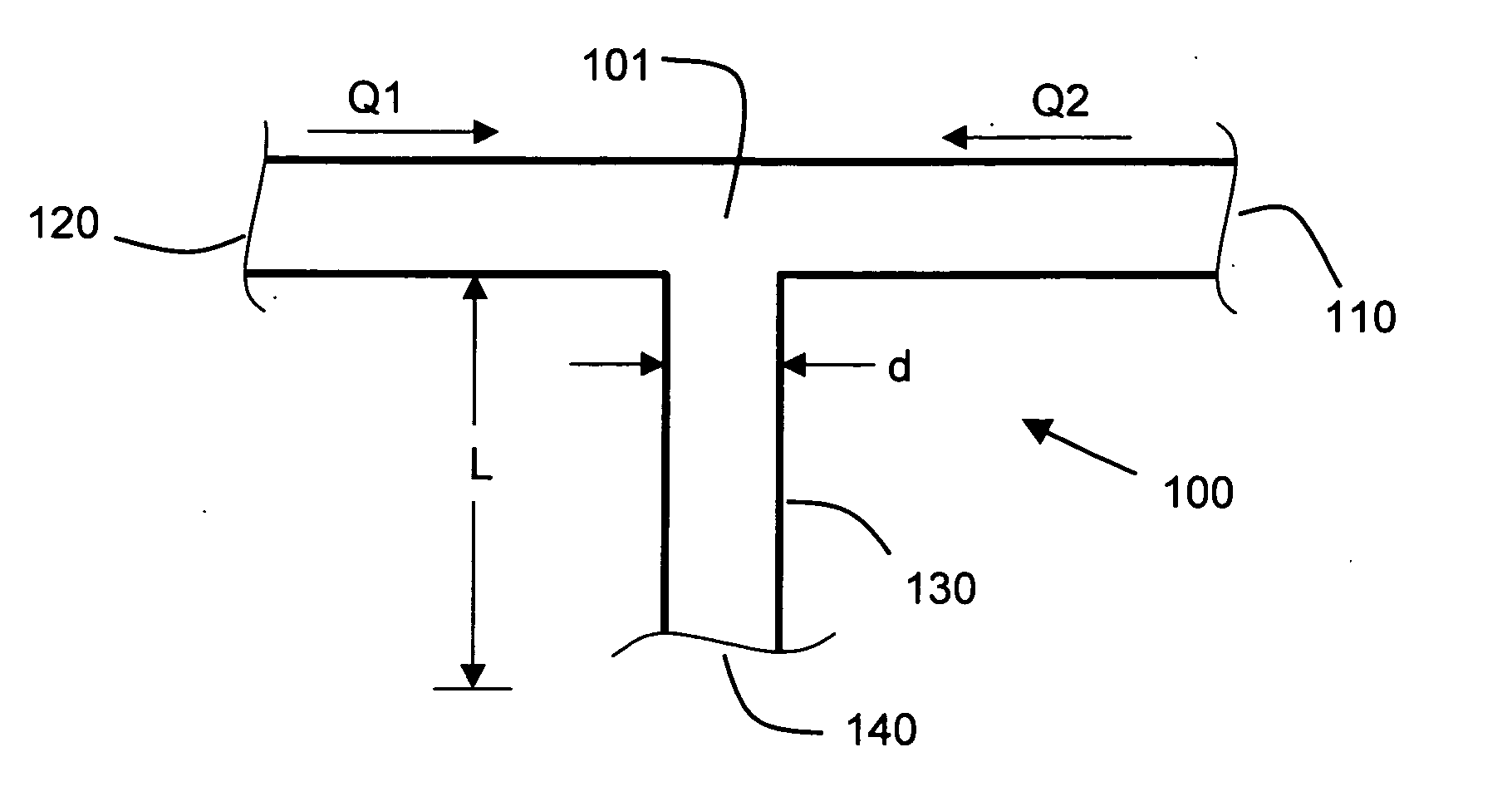
[0137] Consider a round conduit having a diameter, d, of 0.05 mm, a total flow rate, Q, of 10 microliters per minute and a diffusion coefficient, D, of 10−9 m2 / s (a value typical of water diffusing into water). According to the prescription above, the length, L, of the mixing conduit is preferably taken to be greater than BQ / 8D corresponding to about 4.2 cm. The volume of the conduit having this length is about 0.082 microliters and the flow delay time is about 0.5 seconds. The one-on-e full width time blur is about d2 / 8D (about 0.32 seconds for the example parameters provided).

[0138] The example just given shows a mixer with a high degree of mixing that is suitable for gradient times as fast as 5 to 10 seconds. The pressure drop through this mixer at the example flow rate is about 5.5 psi which favorably compares to typical pressure drops of 500 to 2000 psi through a separation column.

example 2

High-Flow Rate Mixer

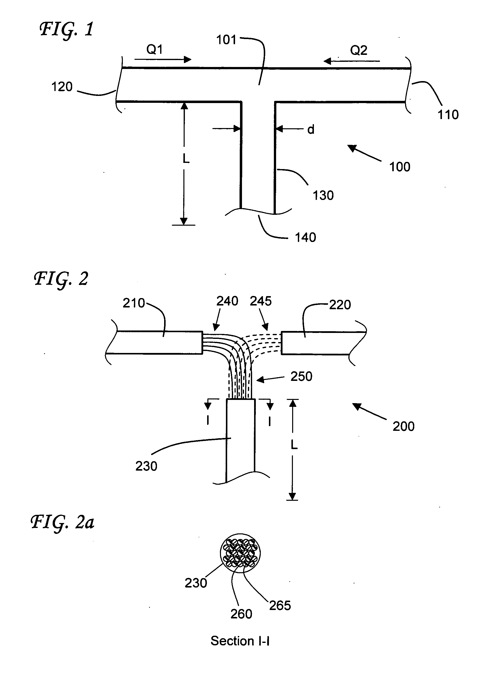
[0139] Consider a round conduit having a diameter, d, of 0.05 mm, a total flow rate, Q, of 1 mL / min and a diffusion coefficient, D, of 10−9 m2 / s (a value typical of water diffusing into water), N=10 and an alternating array bundle. The length, L, of the mixing conduit is on the order of about 4.2 cm. It will be appreciated that the issues of delay time and of axial dispersion that give rise to time-blur begin at the point of mixing. Using sub-divided input streams results in a substantial reduction of the mixing conduit length, L, and concomitant reductions in delay time and time blur.


PUM


Abstract

Methods and apparatus for mixing fluids are provided. The devices and methods operate without moving parts, and generate well-mixed fluids over a broad dynamic range of flow rates. Preferred embodiments include junction-type mixers, bundled mixers, and co-axial mixers. The devices and methods are optimized to produce rapid, accurate gradients to improve associated system throughput and reproducibility.

Description

CROSS REFERENCE TO RELATED APPLICATIONS [0001] Not applicable. STATEMENT REGARDING FEDERALLY SPONSORED RESEARCH OR DEVELOPMENT [0002] Not applicable. BACKGROUND OF THE INVENTION [0003] 1. Field of the Invention [0004] The invention relates to methods and apparatus for fluid mixing. [0005] 2. Description of the Related Art [0006] Devices for mixing fluids are known in the art. In general, such devices can be characterized as active or passive fluid mixers. Active fluid mixers take advantage of mechanical or other means to provide agitation or stirring. U.S. Pat. No. 6,482,306, titled “Meso- and Microfluidic Continuous Flow and Stopped Flow Electroosmotic Mixer” describes an electroosmotic mixing device for use in meso- or microfluidic device applications. The degree of mixing provided by that disclosed device is affected by choice of materials for the chargeable surface and the ionic strength of the fluids and the type and concentration of ions in the fluids. U.S. Pat. No. 6,086,243,...

Claims


Application Information

Patent Timeline
Patent Type & Authority Applications(United States)
IPC IPC(8): B01D15/08B01D15/16B01F5/02B01F5/04B01F13/00B01J4/00B01J19/00
CPCB01D15/166B01F5/0256B01F5/045B01F13/0059B01F13/0066B01J2219/00995B01J4/002B01J19/0093B01J2219/0086B01J2219/00889B01J2219/00891B01J4/001B01F25/23B01F25/313B01F33/3012B01F33/30
Inventor ARNOLD, DON W.PAUL, PHILLIP H.
Owner EKSIGENT TECH
Why Eureka
Try Eureka