

Light ray cut filter
a filter and light ray technology, applied in the field of ray cut filters, can solve problems such as difficulty in adjusting a point, and achieve the effects of preventing and suppressing a change amount of transmittan
- Summary
- Abstract
- Description
- Claims
- Application Information
AI Technical Summary
Benefits of technology
Problems solved by technology
Method used
Image

Examples
embodiment 1
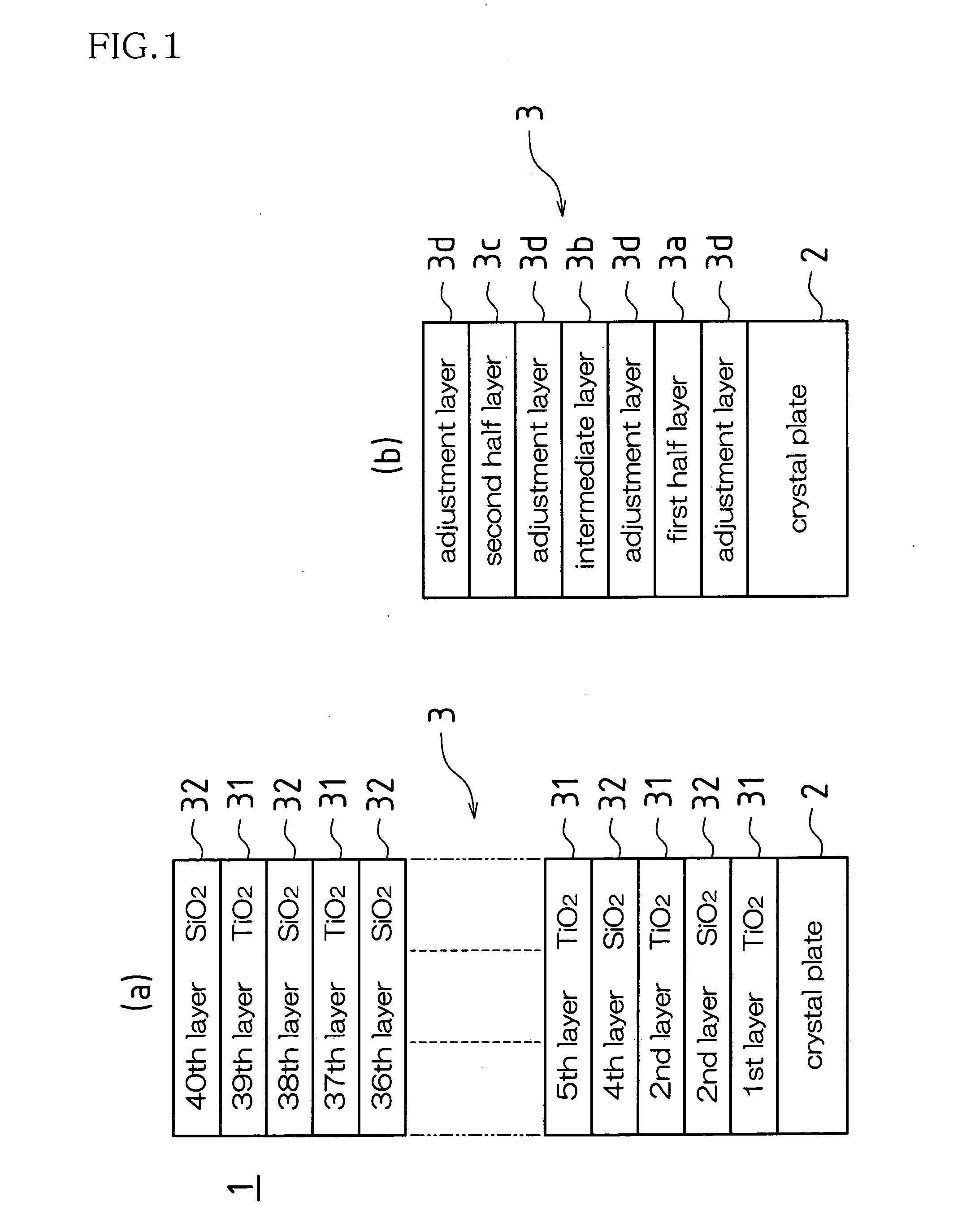
[0044] As shown in FIG. 1(a), an IR-cut filter 1 according to Embodiment 1 of the present invention comprises a crystal plate 2, which is a transparent plate, and a multilayer film 3, which is formed on one side of the crystal plate 2.
[0045] The multilayer film 3 is composed of first thin films 31 made of a high refractive index material and second thin films 32 made of a low refractive index material, which are alternately layered. Specifically, odd-numbered layers counted from this side of the crystal plate 2 are composed of the first thin film 31, while even-numbered layers are composed of the second thin film 32. It should be noted that, in Embodiment 1, TiO2 is used for the first thin film, while SiO2 is used for the second thin film.
[0046] The multilayer film 3 is fabricated as follows. TiO2 and SiO2 are vacuum deposited alternately on one side of the crystal plate 2 using a well-known vacuum deposition apparatus (not shown) to form the multilayer film 3 as shown in FIG. 1(a...
example 1
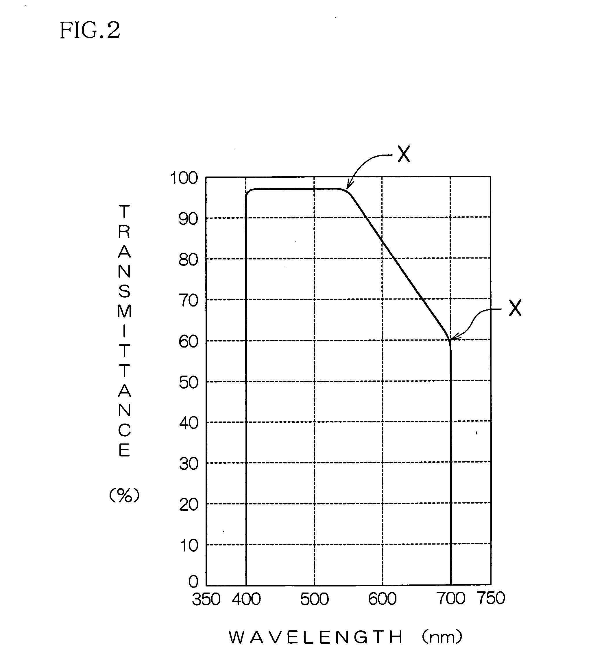
[0055] In Example 1, a crystal plate 2 having a refractive index of 1.54 was used as a transparent plate. Also, TiO2 having a refractive index of 2.30 was used as the first thin film 31 and SiO2 having a refractive index of 1.46 was used as the second thin film 31. The center wavelength of these layers was set to 700 nm.
[0056] The thin films 31, 32 are formed by a production method for the multilayer film 3 having 40 layers so that the thin films 31, 32 each have an optical film thickness as shown in Table 1. As a result, transmittance characteristics as shown in FIG. 3 were obtained. It should be noted that the angle of incidence of light is 0 degree, i.e., light is incident normal to the multilayer film 3 in Example 1.
TABLE 1centerdepositedrefractiveoptical filmwavelengthlayermaterialindex Nthickness Ndλ (nm)1TiO22.301.207002SiO21.461.057003TiO22.301.057004SiO21.461.057005TiO22.301.057006SiO21.461.057007TiO22.301.127008SiO21.461.127009TiO22.301.1270010SiO21.461.1270011TiO22.301...
embodiment 2
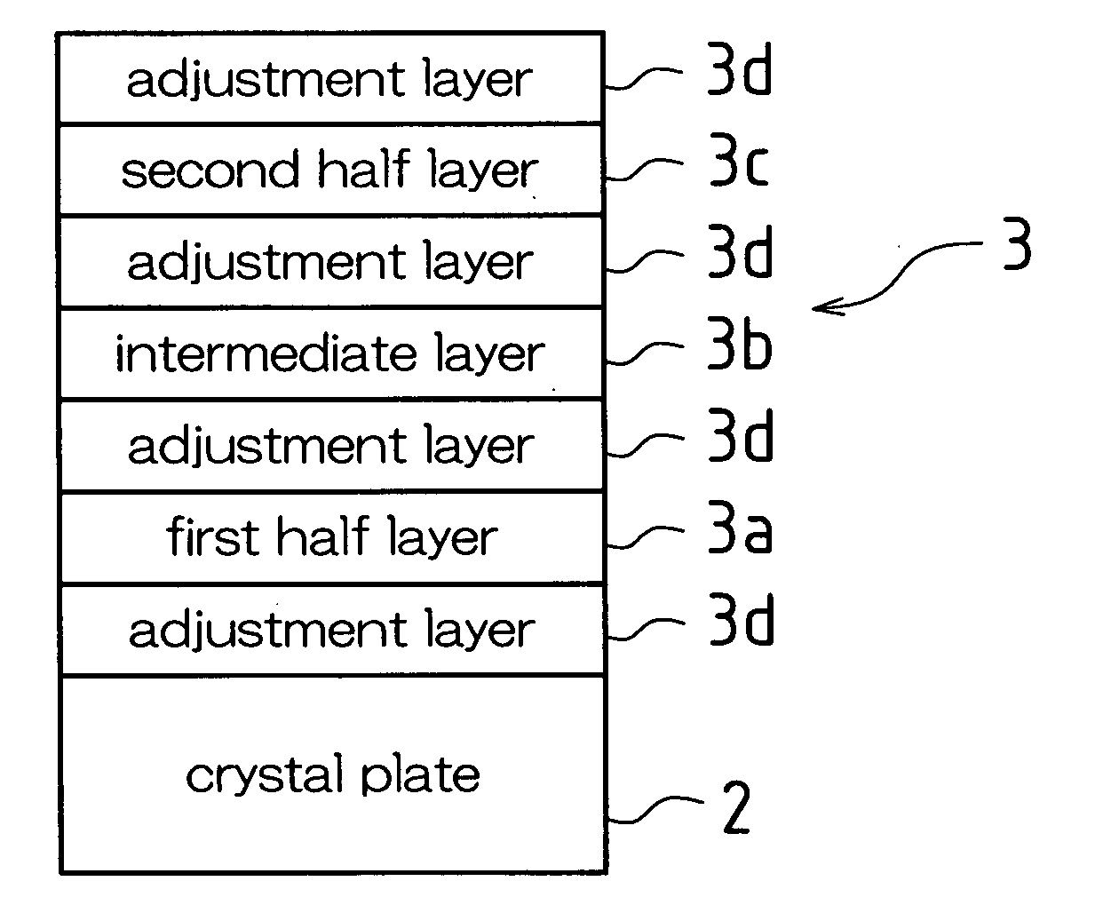
[0074] An IR-cut filter according to Embodiment 2 has the same structure as that of the above-described IR-cut filter 1 of Embodiment 1, except for the first layer 3a, the second layer 3b, the third layer 3c, and the adjustment layer 3d. Therefore, in Embodiment 2, the different first layer 3a, second layer 3b, third layer 3c and adjustment layer 3d will be described. The same parts are referenced with the same reference numerals and will not be explained.
[0075] A multilayer film of the IR-cut filter 1 of Embodiment 2 is composed of a first layer 3a, a second layer 3b and a third layer 3c sequentially from one side of a crystal plate 2 as shown in FIG. 1(b). Each of the first layer 3a, the second layer 3b and the third layer 3c is composed by layering a first thin film 31 and a second thin film 32. Since optical film thicknesses of the layered first and second thin films 31 and 32 differ from layer to layer, the first layer 3a, the second layer 3b, and the third layer 3c have a thi...
PUM
| Property | Measurement | Unit |
|---|---|---|
| Thickness | aaaaa | aaaaa |
| Transparency | aaaaa | aaaaa |
| Wavelength | aaaaa | aaaaa |
Abstract
Description
Claims
Application Information