Flexible mold and method of manufacturing microstructure using the same

Inactive Publication Date: 2005-11-17
3M INNOVATIVE PROPERTIES CO
View PDF14 Cites 35 Cited by
  • Summary
  • Abstract
  • Description
  • Claims
  • Application Information

AI Technical Summary

Benefits of technology

[0066] The flexible mold according to the invention is not solely used for forming the PDP rib but can be advantageously used for forming a variety of microstructures having similar shapes or patterns.

Problems solved by technology

However, since the size of the vacuum press molding machine is limited, it can manufacture a back plate for PDP having a size of only a few cm, and is not suitable for manufacturing PDP to serve as a large display.
In consequence, when the rib is released with the substrate from the metal master mold, the rib is likely to be broken.
According to the existing molding technology, however, it is difficult to manufacture such a mold.
Such bubbles 12 result in rib defects when the ribs are manufactured by using the mold.
As described in Japanese Unexamined Patent Publicatio

Method used


Image

  • Flexible mold and method of manufacturing microstructure using the same
  • Flexible mold and method of manufacturing microstructure using the same
  • Flexible mold and method of manufacturing microstructure using the same

Examples


example 1

[0068] To manufacture a PDP back plate, this example prepares a rectangular metal master mold 5 having partitions 14 of a lattice pattern as typically shown in FIG. 9. The explanation will be given in further detail. This metal master mold 5 is constituted by arranging longitudinal partitions (longitudinal ribs) having an isosceles trapezoidal section in a predetermined pitch in a longitudinal direction and transverse partitions (transverse ribs) having an isosceles trapezoidal section in a predetermined pitch in a direction perpendicular to the longitudinal ribs as tabulated in the following Table 1. The spaces (recess) 15 defined by the partitions 14 in the longitudinal and transverse directions are discharge display cells of PDP.

TABLE 1pitchheighttop widthbottom widthtaper anglelongi. rib300 μm208 μm55 μm115 μm82°trans. rib500 μm208 μm37 μm160 μm75°

[0069] A first curable material is prepared by mixing 80 wt % of aliphatic urethane acrylate oligomer (a product of Henkel Co., tra...

example 2

[0075] A flexible mold is manufactured and inspected in the same way as in Example 1 with the exception that the first curable material on the support film is laminated with the second curable material on the metal mast mold in such a fashion that the distance from the upper surface of the top of the partitions of the metal master mold to the support film is 55 μm.

[0076] In the flexible mold of this example, existence of bubbles and deformation of the pattern cannot be confirmed, either.

example 3

[0077] A flexible mold is manufactured and inspected in the same way as in Example 1 with the exception that the second curable material having a viscosity of 200 cps at 22° C. is prepared by mixing 50 wt % of Photomer 6010, 50 wt % of 1,6-hexanediol diacrylate and 1 wt % of Darocure 1173.

[0078] In the flexible mold of this example, existence of bubbles and deformation of the pattern cannot be confirmed, either.


PUM

PropertyMeasurementUnit
Temperatureaaaaaaaaaa
Flexibilityaaaaaaaaaa
Microstructureaaaaaaaaaa

Abstract

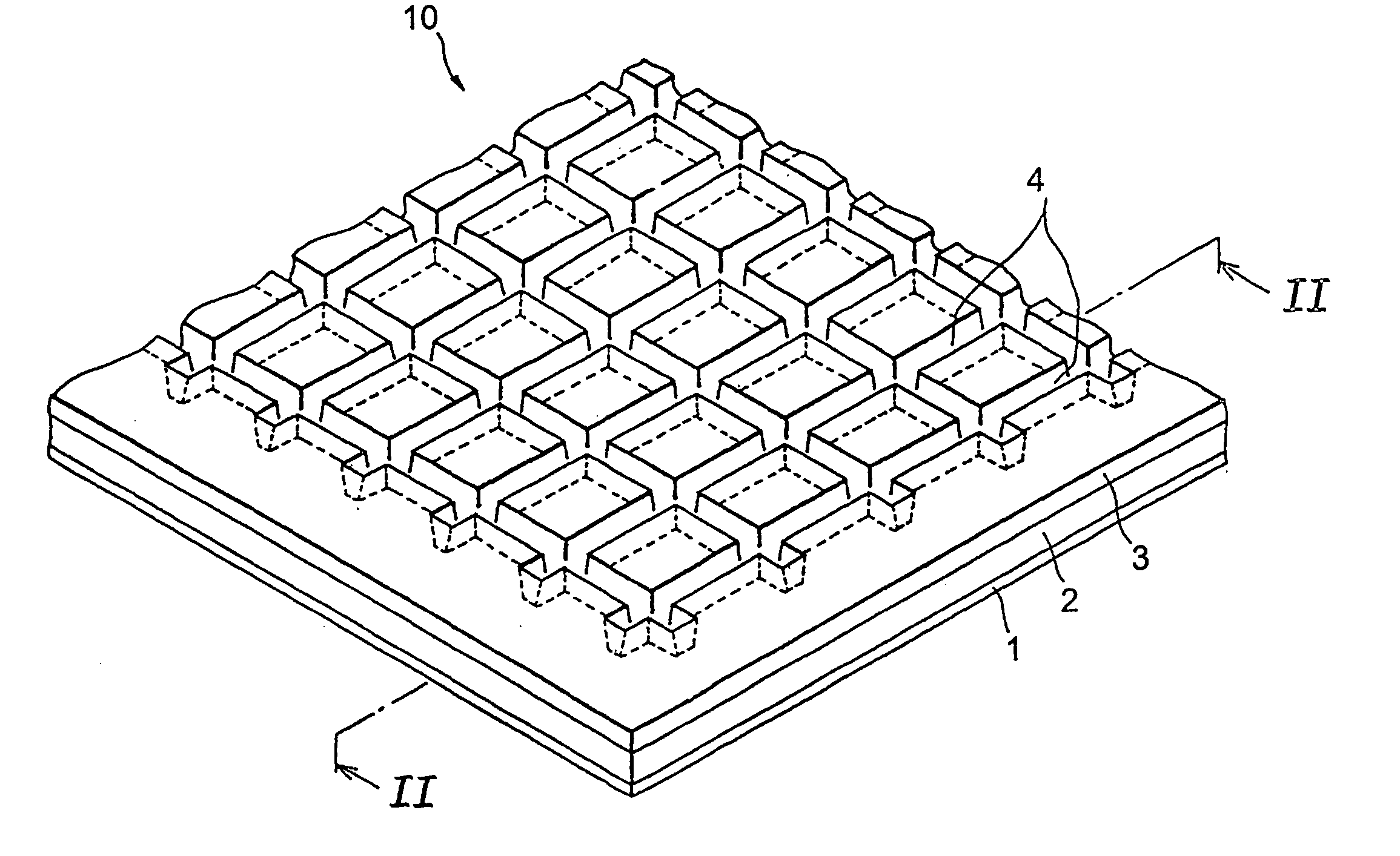
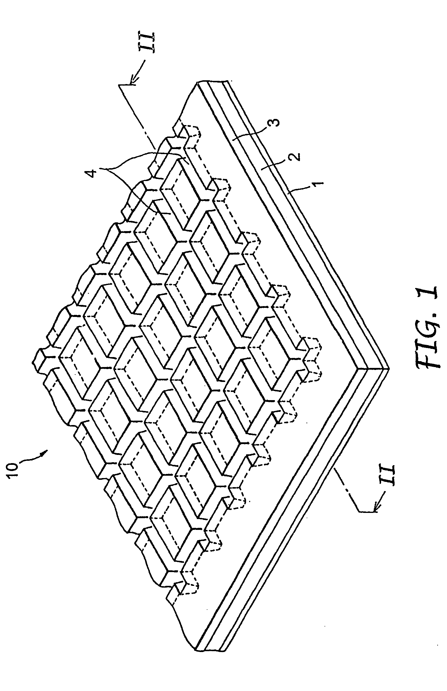
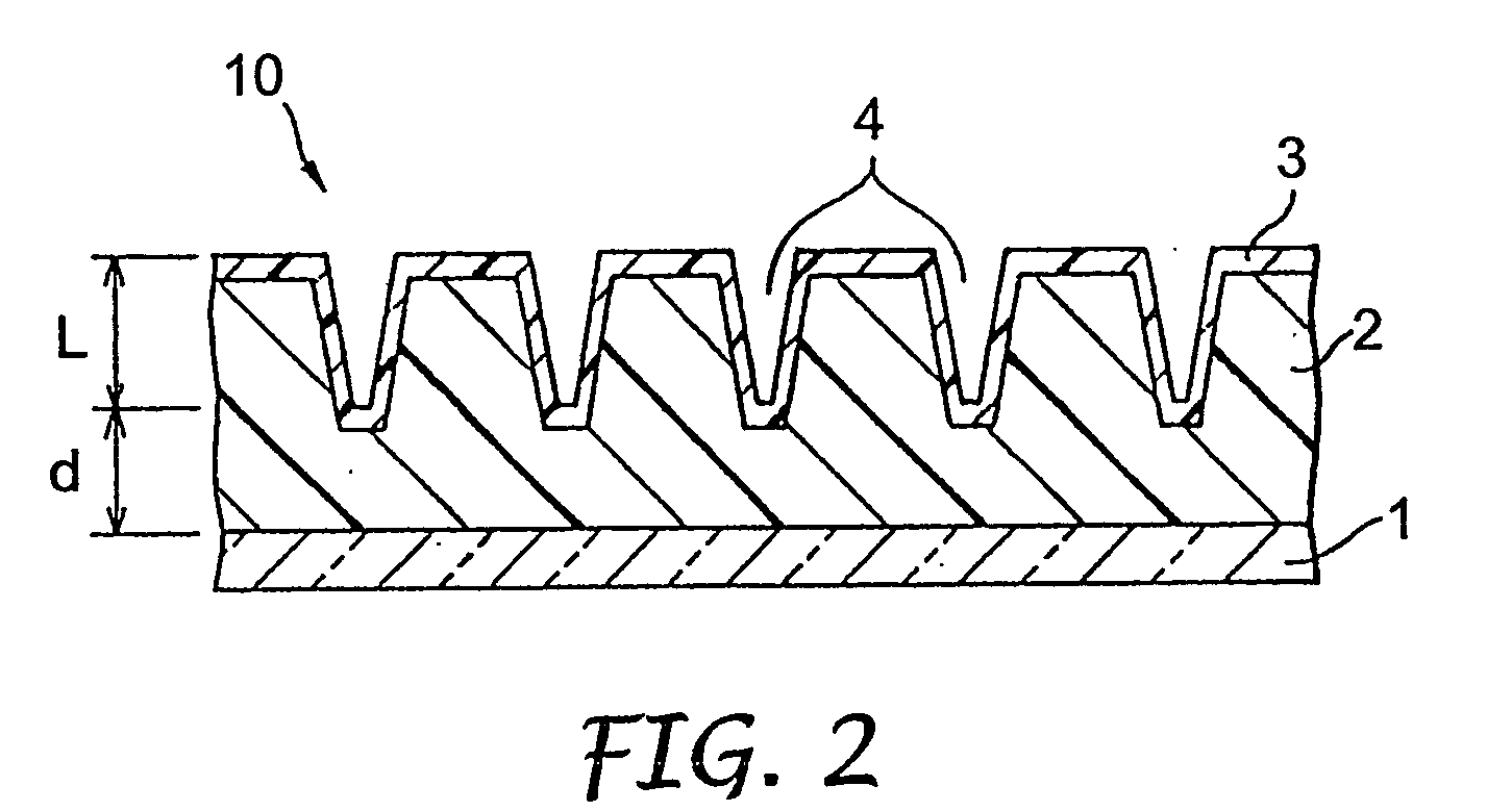
To provide a flexible mold (10) useful for manufacturing a PDP rib having a lattice pattern and other microstructures, and capable of highly precisely manufacturing the microstructures without involving defects such as occurrence of bubbles and pattern deformation. A flexible mold (10) comprises a base layer (2) made of a first curable material having a viscosity of 3,000 to 100,000 cps at 10 to 80° C. and a coating layer (3) coating a surface of the base layer (2) and made of a second curable material having a viscosity of 200 cps or below at 10 to 80° C.

Description

FIELD OF THE INVENTION [0001] This invention relates to a molding technology. More particularly, this invention relates to a flexible mold and to a manufacturing method of a micro-structure using the flexible mold. The manufacturing method of a microstructure according to the invention is advantageous for manufacturing a rib of a back plate of a plasma display panel, for example. BACKGROUND [0002] Display devices of a cathode ray tube (CRT) have economically been mass-produced owing to the progress and development of television technologies achieved up to this date, as is well known in the art. In recent years, however, a thin and lightweight flat panel display has drawn an increasing attention as a display device of a next generation that will replace the display devices of the CRT. [0003] One of the typical examples of such flat panel displays is a liquid crystal display (LCD), and the LCD has already been used as a compact display device of notebook type personal computers, cellu...

Claims


Application Information

Patent Timeline
IPC IPC(8): B29C33/38H01J9/02B29C33/40B29C33/42B29C35/08B29C37/00B29C39/10B29D11/00H01J9/24H01J11/22H01J11/34H01J11/36
CPCB29C33/3857B29C33/40B29C33/424B29C35/0888H01J2217/49264B29C2035/0827B29D11/0074B29L2031/3475H01J9/242B29C37/0053B29C33/42H01J9/24
Inventor YOKOYAMA, CHIKAFUMIYODA, AKIRAKIKUCHI, HIROSHI
Owner 3M INNOVATIVE PROPERTIES CO
Why Eureka
Try Eureka