Shaft member with vibration damping function

Inactive Publication Date: 2005-11-17
THK CO LTD
View PDF2 Cites 26 Cited by
  • Summary
  • Abstract
  • Description
  • Claims
  • Application Information

AI Technical Summary

Benefits of technology

[0008] The present invention has been made in view of problems like those described above. An object of the present invention is to provide a shaft

Problems solved by technology

However, the following problem may occur when using the ball screw devices, the ball splines, or the like.
If the settling time for the vibrations to subside is long, there are problems in that the tact time for completing one work unit becomes longer, and the manufacturing efficiency decreases.
A circumferential wall of the hollow shaft is formed by laminating an intermediate layer of a ceramic material between an inner layer a

Method used


Image

  • Shaft member with vibration damping function
  • Shaft member with vibration damping function
  • Shaft member with vibration damping function

Examples


Example

[0018]8 . . . tie rod (shaft member), 8a . . . hollow portion, 8b . . . shaft main body, 8c . . . vibration absorbing member

BEST MODES FOR CARRYING OUT THE INVENTION

[0019] A shaft member provided with a vibration damping function according to the present invention is explained in detail below based on the appended drawings.

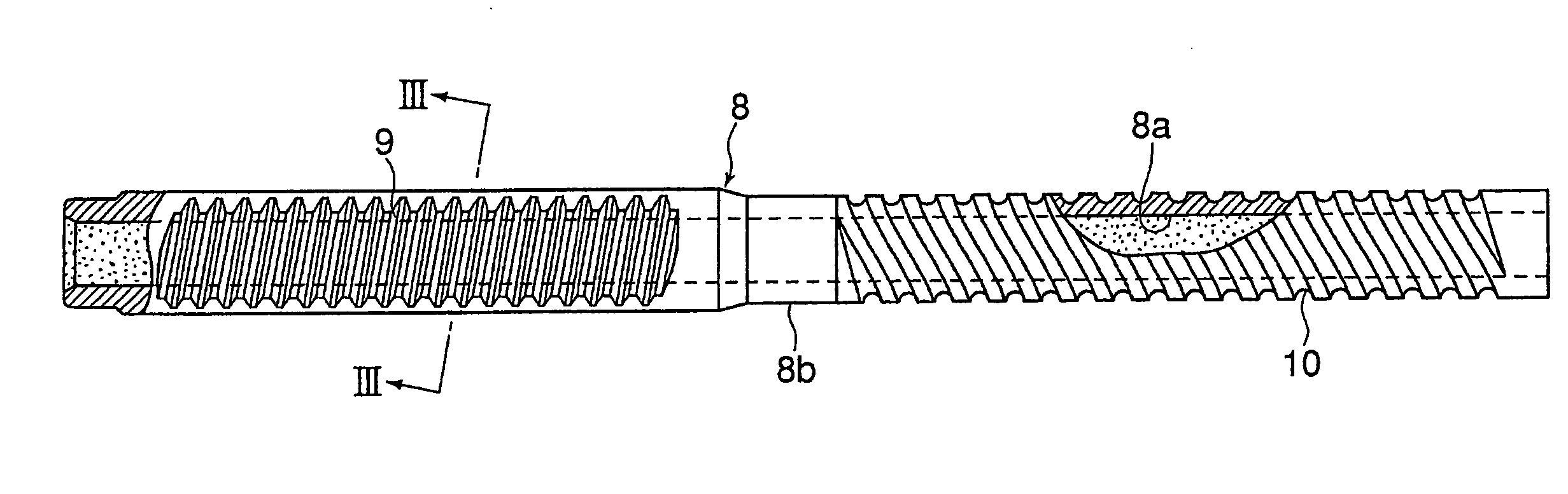
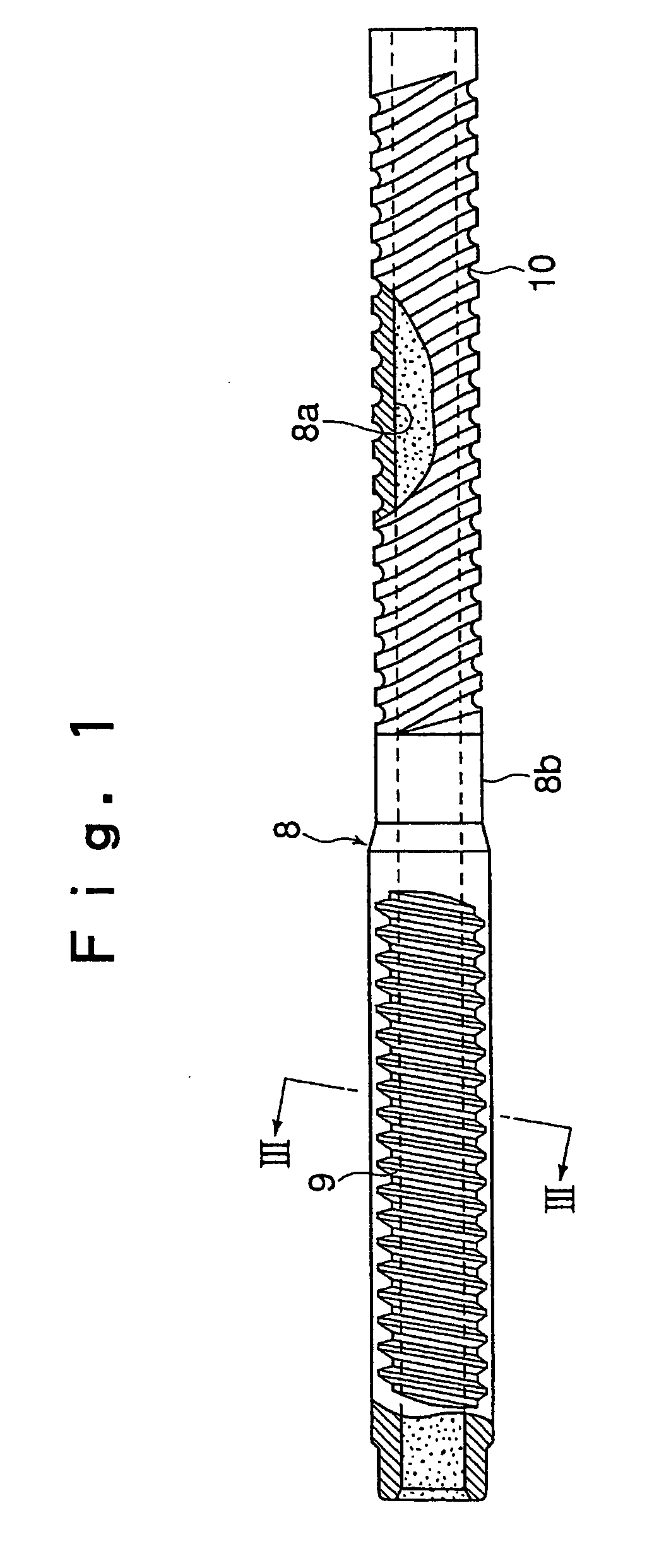
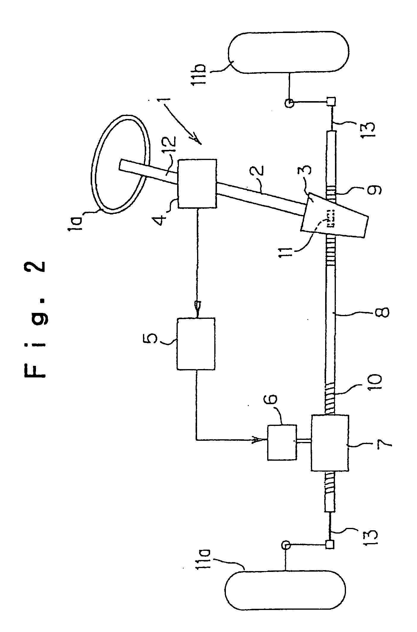
[0020]FIG. 1 is a drawing that shows an example of a tie rod 8 used in a power steering apparatus of a vehicle. As shown in FIG. 2, the power steering apparatus to which the tie rod 8 is applied includes a steering system 1, a rack and pinion mechanism 3 that is connected to an output shaft 2 of the steering system 1, steering torque detecting means 4 for detecting a steering torque of the steering system 1, controlling means 5 for generating a control signal based on a signal detected by the steering torque detecting means 4, an electric motor 6 that generates an auxiliary torque in accordance with the steering torque based on the control signal of the control...


PUM


Abstract

Provided is a shaft member capable of minimizing the occurrence of noise by positively attenuating vibration acting on a metal shaft member having spline grooves and spiral grooves axially formed therein. To attain such an object, a shaft member includes a metal shaft main body having a hollow portion and a ceramic material serving as a vibration absorbing member which fills the hollow portion of the shaft body with no gaps. The ceramic material is filled into the hollow portion of the shaft main body in a powder, granular, or fluid state, and formed within the hollow portion into a shape matching the hollow portion.

Description

TECHNICAL FIELD [0001] The present invention relates to a shaft member made of metal, in which a spline groove, a helical groove, and the like are formed along an axial direction thereof. In particular, the present invention relates to improvements in order to attenuate vibrations or noise at an early stage. BACKGROUND ART [0002] For example, there are known conventional ball splines that include a spline shaft in which ball rolling grooves are formed along an axial direction, and a spline nut that fits together with the spline shaft through endlessly circulating balls, in which the spline nut is free to move in the periphery of the spline shaft along the axial direction and in which torque transmission between the spline shaft and the spline nut is possible. [0003] Further, there are known conventional ball screw devices that include a screw shaft with helical ball rolling grooves formed at a predetermined pitch therein, and a screw nut that fits together with the screw shaft throu...

Claims


Application Information

Patent Timeline
IPC IPC(8): B62D3/12B62D5/04F16C3/02F16F7/01F16H25/24
CPCB62D3/126B62D5/0445F16H25/24F16F7/01F16C3/02F16C2326/24
Inventor MICHIOKA, HIDEKAZUNIWA, HIROSHITAMANO, MASAHIKO
Owner THK CO LTD
Why Eureka
Try Eureka