Surgical pneumatic motor

a pneumatic motor and surgical technology, applied in the field of pneumatic motors, can solve the problems that the motor for some medical procedures does not meet the needs of surgeons, and achieve the effects of minimal lubrication, good feel characteristics, and no sacrificing siz

Active Publication Date: 2005-11-17
ANSPACH EFFORT
View PDF5 Cites 21 Cited by
  • Summary
  • Abstract
  • Description
  • Claims
  • Application Information

AI Technical Summary

Benefits of technology

[0027] In addition to the aforementioned features this invention includes an improved sealing that is formed in situ, inclusion of slots on the cylinder for cooling, suspension of the insert motor case, resilient coupling of the output shaft to the motor drive, isolation of the motor and lock shaft so that vibration of the cutter are not transmitted to the motor and the invention is characterized as providing additional power without sacrificing size, is cooler, has good feel characteristics to the user, requires minimal lubrication and has increased operating life. Because of the modular design of the motor, the chuck portion of the motor where the attachment and cutting tools are attached can be removed without having to dismantle the remaining portion of the motor. This facilitates the maintenance where heretofore the motor had to be disassembled in order to work on the chuck portion, which requires more maintenance than the motor portion.

Problems solved by technology

However, this motor for some medical procedures does not meet the needs of the surgeons because it lacked the necessary power which gave rise to the Micro Max Plus motor, which, again, has more power than the Micro Max but, yet, less power than the Black Max.

Method used


Image

  • Surgical pneumatic motor
  • Surgical pneumatic motor
  • Surgical pneumatic motor

Examples


Embodiment Construction

[0053] While this invention is being shown in its preferred embodiment having elements that are designed to meet certain specifications to improve on the surgical drill, it will be appreciated that some elements may undergo changes and replacements as the instrument is being developed and these changes will be in the scope of this invention.

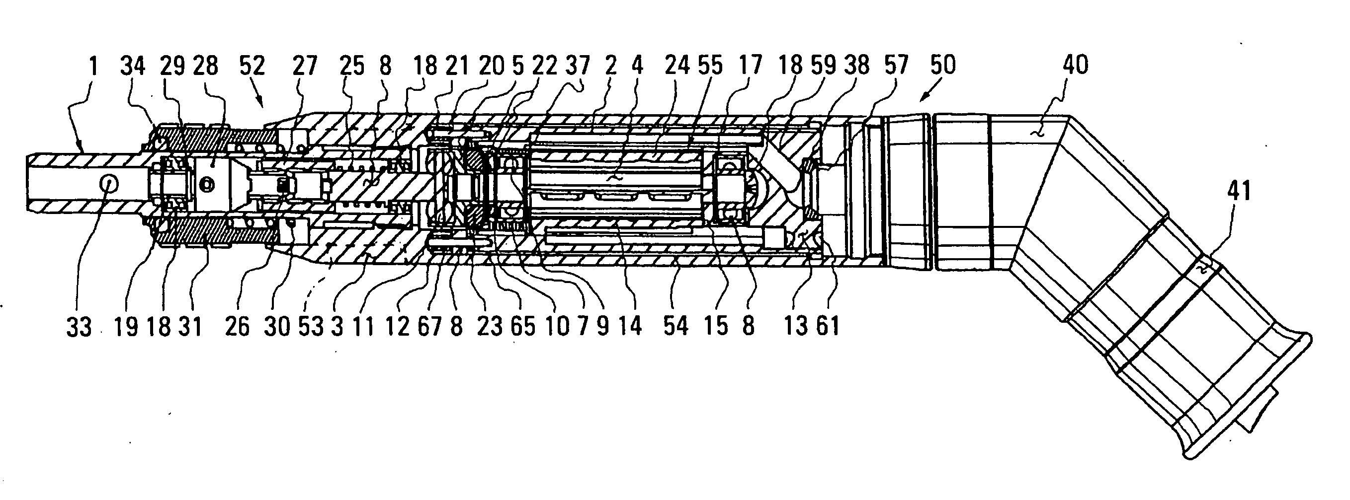
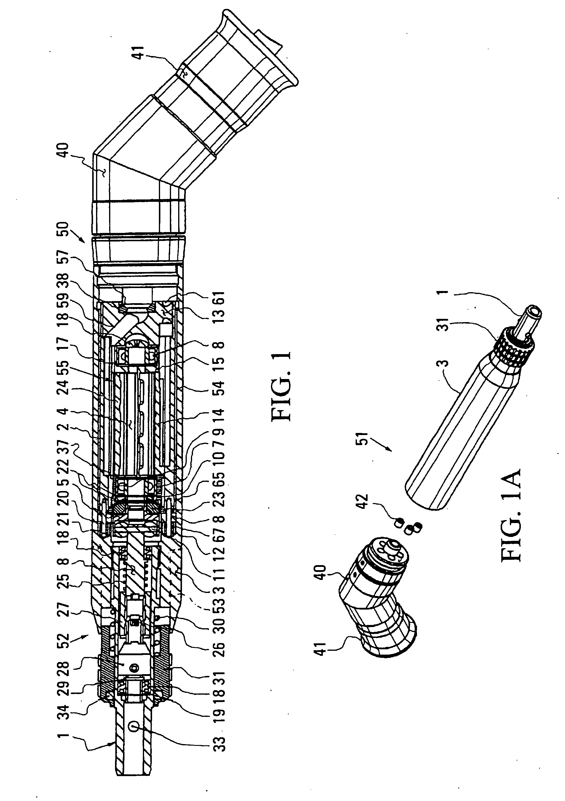
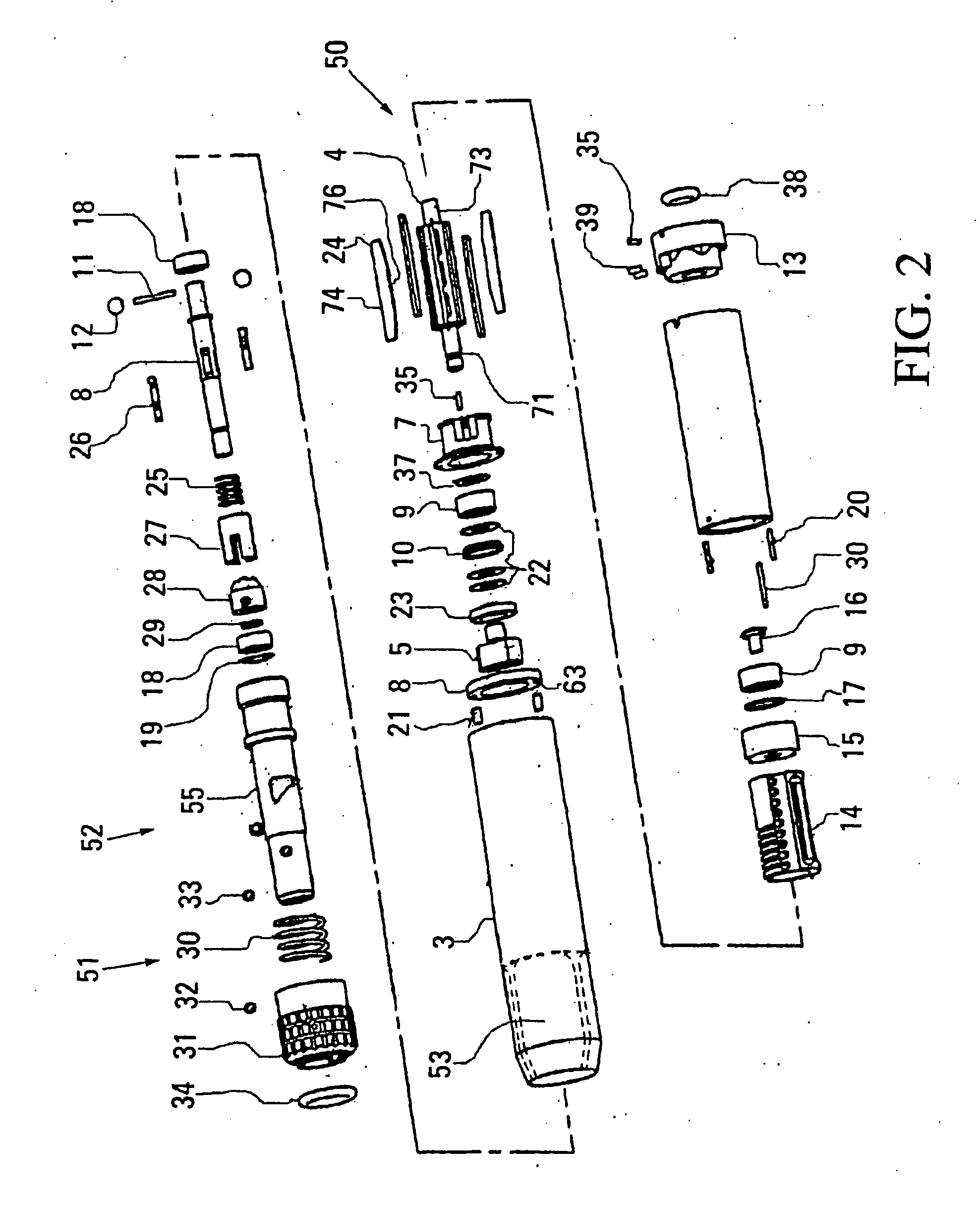
[0054] The invention can best be understood by referring to FIGS. 1 and 2 showing the elements of the invention in an exploded view and then showing these same elements in the assembled condition comprising housing tube 1, insert or inner housing 2, motor or outer housing 3, spindle 4, coupling nut 5, pawl driven or output shaft (6), seal / bearing housing 7, isolation washer 8, bearing 9, support washer 10, drive pin 11, coupling ball 12, motor adapter 13, cylinder 14, back plate 15, machine screw 15, wave washer 17, bearing 18, wave washer 19, dowel pin 20, torque pin pad 21, seal 22 and 22a, seal retaining nut 23, vane 24, spring 25, pawls 26, ...


PUM


Abstract

A surgical motor designed to for power, noise and heat reduction for powering surgical tools where the surgical motor is modular constructed to house the vane motor for generating power in one module and the chuck and output shaft in the other module. A coupling mechanism for transmitting rotary motion from the vane motor to the output shaft includes balls made from elastomeric material to reduce vibrations and noise. The vane motor includes vanes that are contoured on the bottom edge, the spindle is undercut adjacent the vanes and peripheral edge of the spindle is grooved to enhance power, the inlet opening to the vanes are repositioned to increase the volume of inlet air, the inner surface is contoured to define a crescent seal adjacent to the spindle outer surface, the inlet and outlet to the spindle are repositioned to increase the power stroke of the vane, the discharge holes are oriented so that the vane edge sees a uniform contact surface during each revolution, the cylinder includes flow passages for cooling the cylinder and for flowing a portion of the air over the support bearings mounted downstream of the cylinder and including a return passageway to feed the inlet holes so that all pressurized inlet air are directed to impinge on the vanes and seal means, one made operable in situ and the other operating adjacent the inner race of the bearing prevents leakage of oil into ambient and into path of the surgical tool and the surgical motor includes an insert housing radially spaced from the main housing defining an air gap for reducing heat and the in the handle and resilient mounting means to isolate the vibrations to reduce noise and a thrust path bypassing the vane motor.

Description

[0001] This application claims the benefits under 35 U.S.C. §119(e) of the U.S. provisional patent application 60 / 567,188 filed on Apr. 30, 2004.CROSS REFERENCES [0002] This invention relates to a the pneumatic motor that is designed be used in an MRI environment SURGICAL MOTOR USED WITH MRI, and is commonly assigned to The Anspach Effort, Inc. and was invented by myself and identified as Attorney Docket No. N943NP, and was filed as a provisional application 60 / 567,189 on Apr. 30, 2004 and is incorporated herein by reference. FEDERALLY SPONSORED RESEARCH [0003] None. TECHNICAL FIELD [0004] This invention relates to pneumatic motors for use by surgeons for performing surgical procedures that are typical in general surgery, neurosurgery, endoscopic, arthroscopic and the like and more particular to an improved pneumatic motor. BACKGROUND OF THE INVENTION [0005] To best understand this invention, it is helpful to know that the pneumatic motor of this invention is intended to replace thr...

Claims


Application Information

Patent Timeline
Patent Type & Authority Applications(United States)
IPC IPC(8): A61B17/00A61B17/16A61B17/24A61B17/32A61B19/00A61C1/18F16D3/16F16D3/205
CPCA61B17/1622A61B17/1624A61B17/1628A61B17/1646A61B17/32002Y10T464/50A61C1/185F01C1/3446F01C21/00F16D3/2052A61B2017/00544F01C21/08F04C2250/20F01C1/3442F16F15/10
Inventor DEL RIO, EDDY H.PERRY, DOUGLAS A.
Owner ANSPACH EFFORT
Why Eureka
Try Eureka