Apparatus and process for the production of sandwich composite elements

a technology of sandwich composite elements and apparatuses, which is applied in the direction of chemistry apparatus and processes, adhesion processes with surface pretreatment, coatings, etc., can solve the problems of metal/foam composite elements, uneven application of adhesion promoters, and restricted usability of metal composite elements

Active Publication Date: 2005-11-24
COVESTRO DEUTSCHLAND AG
View PDF5 Cites 23 Cited by
  • Summary
  • Abstract
  • Description
  • Claims
  • Application Information

AI Technical Summary

Benefits of technology

[0009] It is an object of the present invention to provide an apparatus and a process for the production of sandwich composite elements, in particular metal / foam composite elements, with which the disadvantages of the prior art are avoided when applying an adhesion promoter.

Problems solved by technology

In addition to inadequate adhesion of the core layer to the facings, another problem encountered with metal / foam composites is encountered in the boundary areas of the foam core layer near the facings where defects arise in the foam, in general in the form of bubbles or altered cell structures.
These defects in the foam may restrict the usability of the metal composite elements and are therefore undesirable.
The known methods for applying the adhesion promoter are sometimes comparatively complex and / or result in uneven application of the adhesion promoter.
In addition, considerable aerosol formation is associated with spray application of the adhesion promoter, leading to the loss of certain quantities of the adhesion promoter, since not all of the sprayed adhesion promoter lands on the facings but is released into the surrounding area instead.
Depending on the type of adhesion promoter, blockage of the extraction apparatus may occur.

Method used


Image

  • Apparatus and process for the production of sandwich composite elements
  • Apparatus and process for the production of sandwich composite elements
  • Apparatus and process for the production of sandwich composite elements

Examples


example

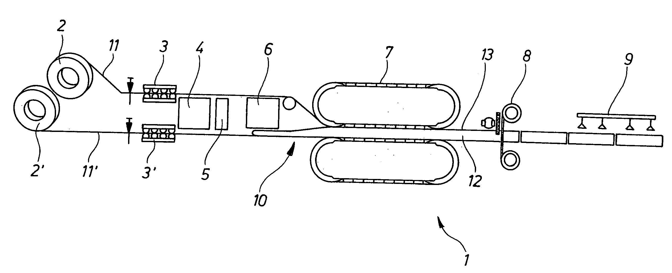
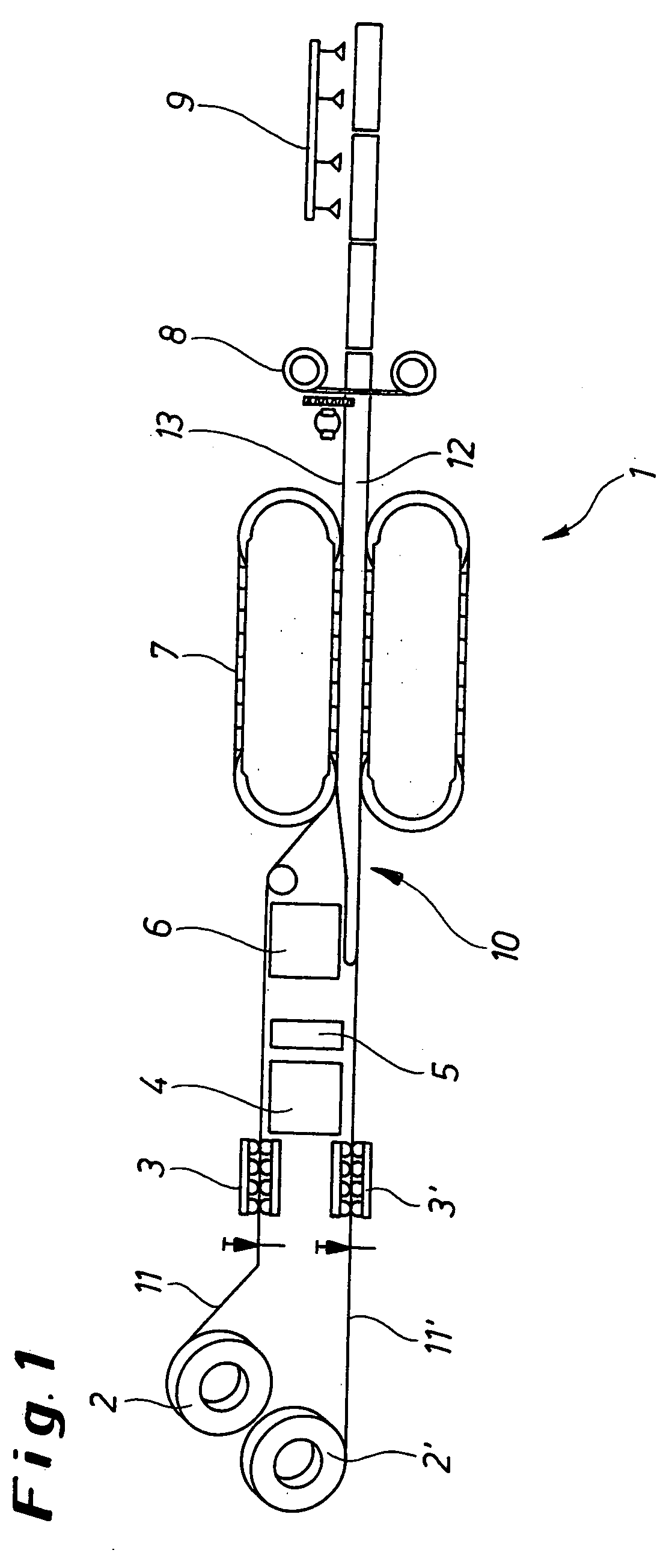
[0049] Metal / foam composite elements with conventional commercial facings of galvanized steel sheet, coated on both sides, and a rigid foam prepared according to the processing recipe stated below using products from Bayer MaterialScience AG, Germany, were produced by means of an apparatus corresponding in structure to that illustrated in FIG. 1.

[0050] Processing recipe and conditions for the foam:

ProductParts by weightBaymer VP.PU 28HB31 Polyol100Desmorapid ® 1792 catalyst3.7Desmorapid VP.PU 27HB332.2catalystAdditive VP.PU 1911F002.8n-Pentane15.5Desmodur ® 44V70 L200isocyanateCream time, sec9Fiber time, sec38Element typeWall, 120 mmBelt temperature, ° C.60

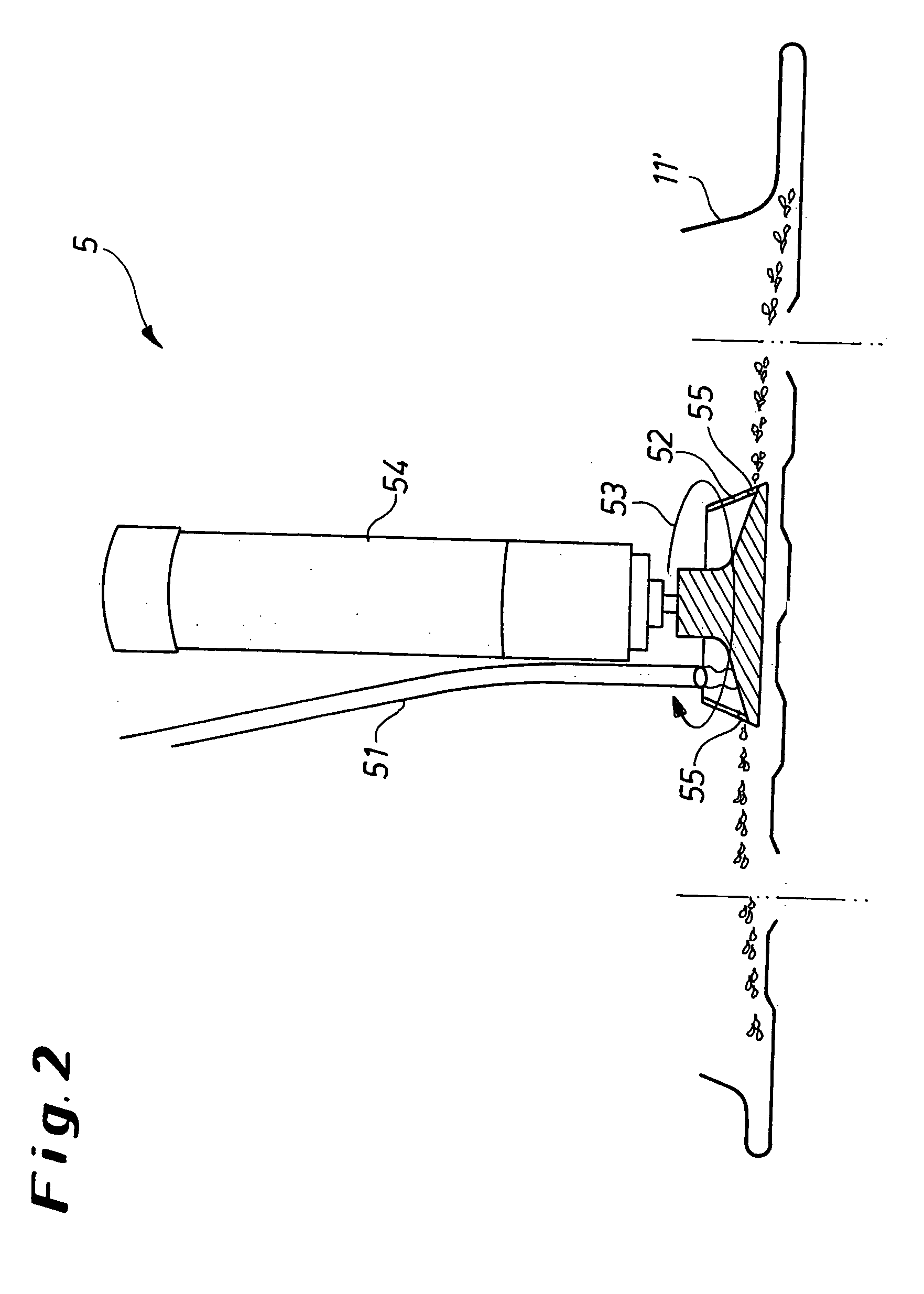
[0051] A two-component polyurethane-based adhesion promoter was used as the adhesion promoter. The isocyanate component was composed of a low viscosity polymeric MDI, Desmodur 44V10 L. A formulation of the following components was used as the polyol component:

59.6 wt. %propylene glycol-propylene oxide polyether, molar mass100...


PUM

PropertyMeasurementUnit
diameteraaaaaaaaaa
diameteraaaaaaaaaa
speedaaaaaaaaaa

Abstract

An apparatus for the production of sandwich composite elements which includes at least two feed apparatus for facings, to which an application apparatus for an adhesion promoter, an application apparatus for a core layer, a conveying apparatus and a cutting apparatus are connected one after the other. The application apparatus for the adhesion promoter includes at least one feed line for the adhesion promoter, a rotary table with at least one lateral outlet orifice and a drive for the rotary table.

Description

BACKGROUND OF THE INVENTION [0001] The present invention relates to an apparatus and to a process for continuous or discontinuous production of sandwich composite elements, in particular metal / foam composite elements. [0002] For the purposes of the present invention, “sandwich composite element” means a composite element composed at least of two facings and a core layer located between the facings. In particular, metal / foam composite elements are made up of at least of two metal facings and a core layer of foam, e.g. a rigid polyurethane (PU) foam. Such metal / foam composite elements having metal facings and a core layer of rigid polyurethane foam are known from the prior art and are sometimes referred to as metal composite elements. Additional layers may be provided between the core layer and the facings. For example, the facings may be finished, e.g., with a coating. [0003] Possible uses for such metal composite elements are, for instance, plane or lined wall elements and profiled ...

Claims


Application Information

Patent Timeline
Patent Type & Authority Applications(United States)
IPC IPC(8): B05B3/10B05C3/10
CPCB05B3/001Y10T156/1052B29C44/129B29C44/32B32B37/1284B32B2038/0084B32B2305/022B32B2311/00Y10T156/1702Y10T156/1343Y10T156/1317Y10T156/1361Y10T156/12Y10T156/1352B05B3/1021B29C44/326B29C44/321
Inventor RUB, THOMASVAN DE BRAAK, JOHANNES
Owner COVESTRO DEUTSCHLAND AG
Why Eureka
Try Eureka