Method and apparatus for manufacture of nanoparticles

a nanoparticle and nanotechnology, applied in the field of special materials, can solve the problems of significant loss of nanoparticles during the evacuation from the reactor, low efficiency, and low process efficiency, and achieve the effect of high production efficiency and high production efficiency

Inactive Publication Date: 2005-11-24
NANOMAT +1
View PDF9 Cites 47 Cited by
  • Summary
  • Abstract
  • Description
  • Claims
  • Application Information

AI Technical Summary

Benefits of technology

[0030] It is an object of the present invention to provide an apparatus for manufacturing nanoparticles that is characterized by improved conditions for the formation of nanoparticles and for collection of the produced nanoparticles. It is another object is to provide the apparatus of the aforementioned type which is characterized by nanoparticles that can be produced in a wide range of types and dimensions. A further object is to provide an apparatus of the aforementioned type, which is characterized by high production efficiency and is suitable for use under industrial conditions. Still a further object is to provide the apparatus of the aforementioned type, which is capable of producing and encapsulating active nanoparticles in a state ready for subsequent use. A further object is to provide a method of manufacturing nanoparticles in a wide range of dimensions and types with high production efficiency.

Problems solved by technology

A disadvantage of the above system is low efficiency and significant losses of nanoparticles during evacuation from the reactor.
However, the process has low efficiency that normally does not exceed 10 g / hr.
Therefore the LAM process is not yet ready for cost-effective commercial application.
In spite of all the advantages of the above-described process and apparatus that make them suitable for industrial application, they still entail some drawbacks.
First, the nozzle, which is used for expansion of the flow of gas with particles at the exit from the nozzle to the thermalization zone, has some thermalization limitations resulting from a subsonic structure of this nozzle.
Therefore, the method and apparatus described above may be inapplicable for a wide range of nanoparticle productions.
A common disadvantage of the methods and apparatuses disclosed in aforementioned patents of Detering, et al. and S. Pirzada is that the diverging portions of the Laval nozzles proposed in these patents have linear tapered profiles and are not optimized with regard to temperatures required for ultra-rapid thermalization of the produced nanoparticles.
Another disadvantage of the aforementioned methods and apparatuses is an imperfect system used for collecting the produced nanoparticles.
Such imperfect system of nanoparticle collection significantly limits the scope of possible practical applications for manufacturing nanoparticles of some specific types.

Method used


Image

  • Method and apparatus for manufacture of nanoparticles
  • Method and apparatus for manufacture of nanoparticles
  • Method and apparatus for manufacture of nanoparticles

Examples


Embodiment Construction

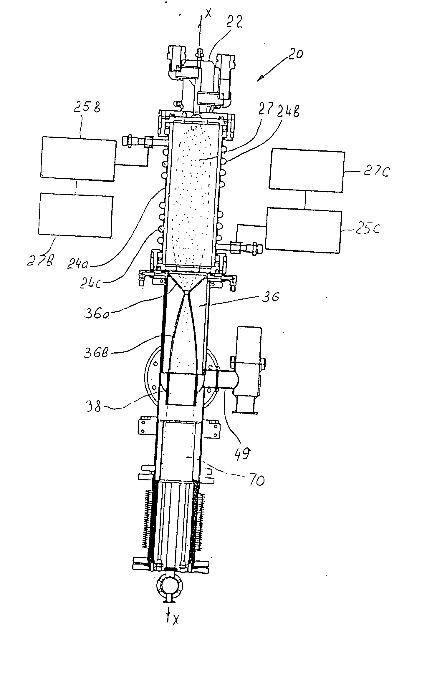
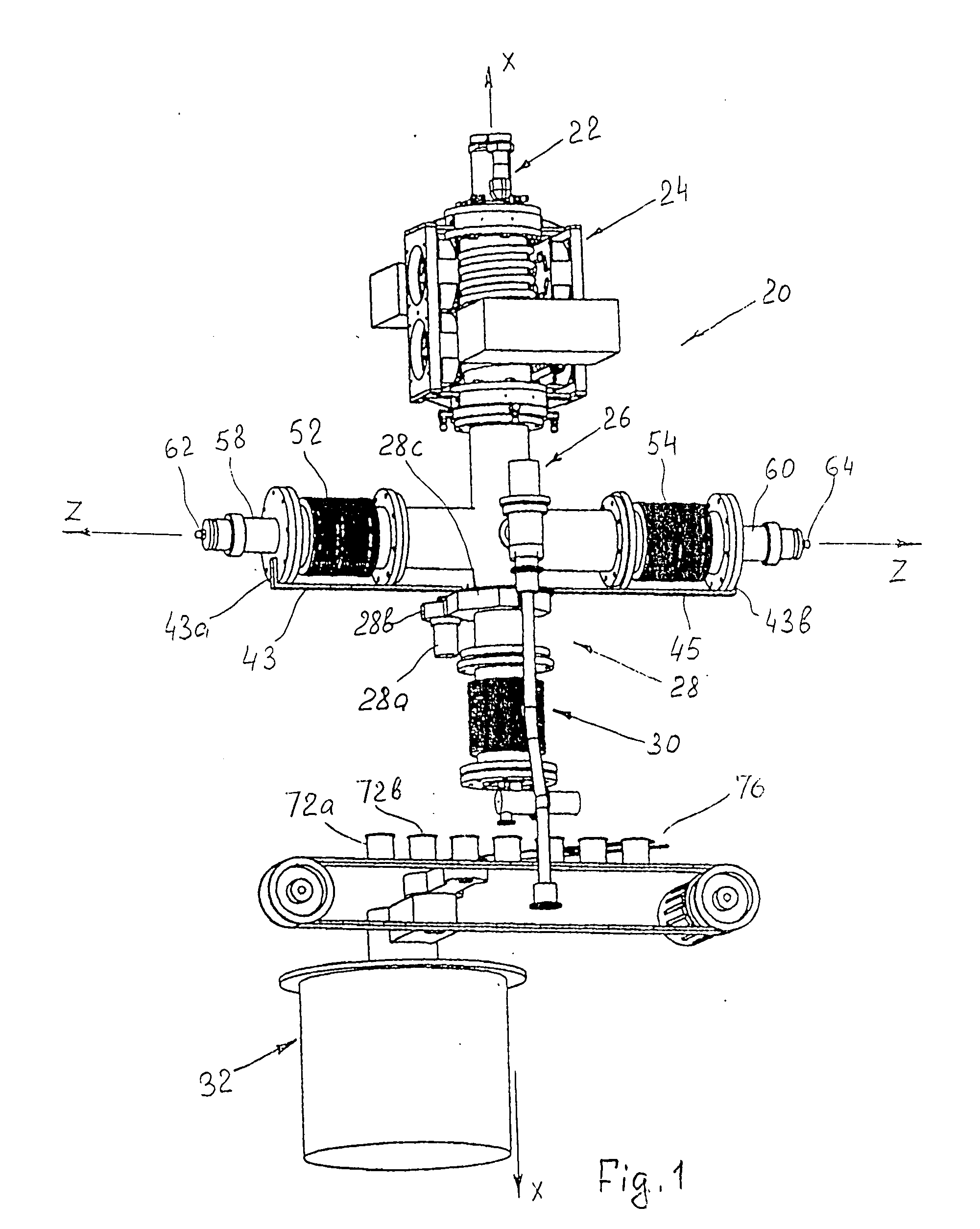
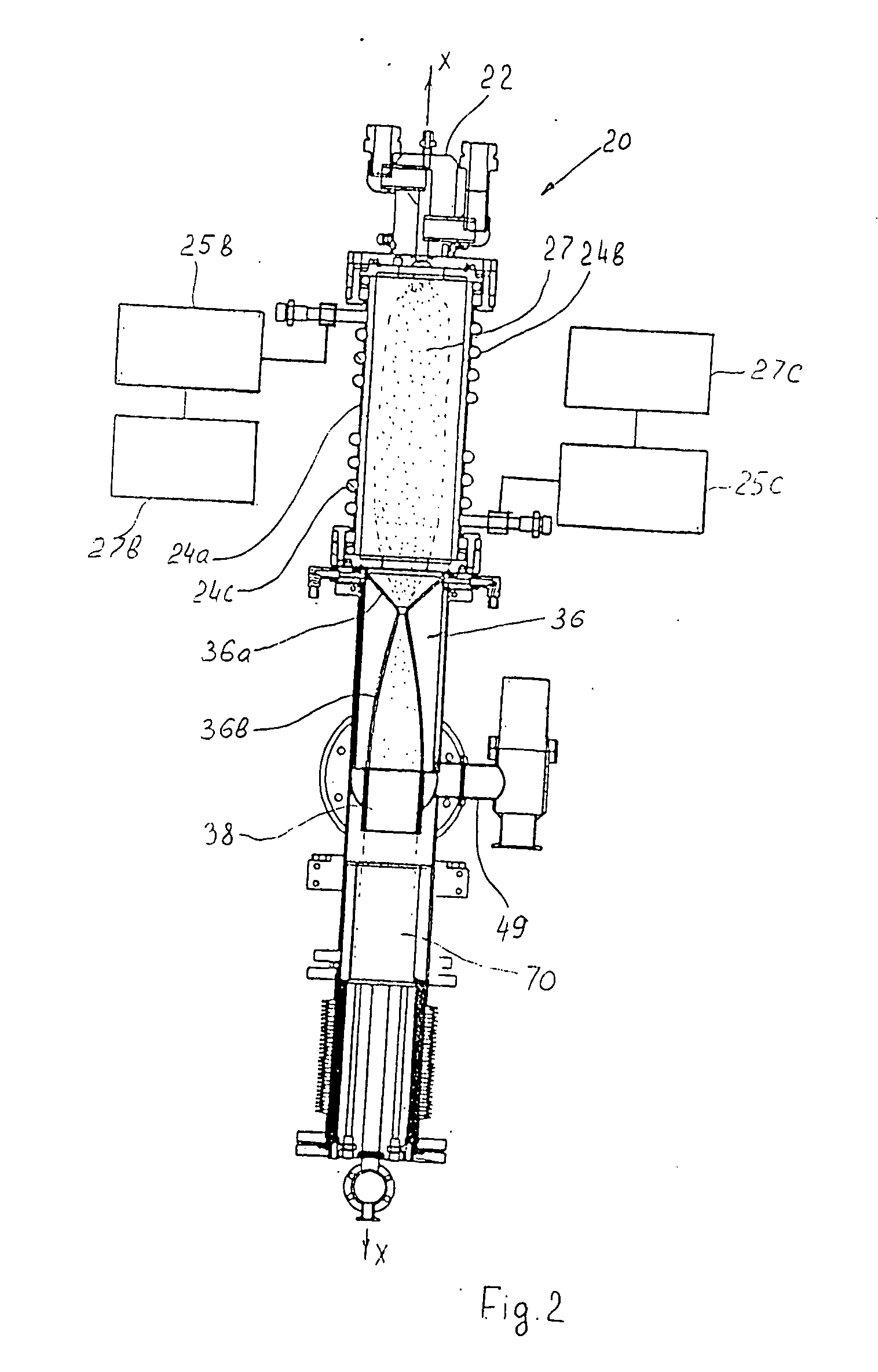
[0040]FIG. 1 is a general three-dimensional view of the apparatus of the invention for manufacturing nanoparticles. The apparatus as a whole is designated by reference numeral 20 and consists of the following main units sequentially arranged in the direction of propagation of the particles: a DC plasma torch initiator 22 into which components of the working mixture (nanoparticle precursor) are supplied; an RF plasma reactor 24, where the plasma chemical reactions for the initiation of the nanoparticle formation from a precursor occur; a Laval nozzle section (only a housing 26 of this section is shown in FIG. 1) for fast quenching and finishing the nanoparticle synthesis at well defined temperature (this process is also known as thermalization); a nanoparicle shielding and ntrapmnt unit 28, which is associated with the outlet end of the Laval nozzle (only rotary reciprocation drive motor 28a with the drive gear 28b and the protective casing 28c of the gear wheel are shown in FIG. 1);...


PUM

PropertyMeasurementUnit
frequenciesaaaaaaaaaa
angleaaaaaaaaaa

Abstract

A method and apparatus for manufacturing nanoparticles by passing a carrying fluid with a nanoparticle precursor through an RF plasma volume for heating the fluid with a nanoparticle precursor to a high temperature sufficient to synthesizing the nanoparticles. The suspension of the fluid with nanoparticles is passed to the thermalization zone in a diverging portion of the Laval nozzle for subjecting the fluid with nanoparticles to jumpwise adiabatic expansion at the exit from the converging portion of the Laval nozzle to the thermalization zone. At least the diverging portion has a curvilinear profile optimized with respect to conditions of said thermalization. In the thermalization zone, the flow of fluid with nanoparticles is surrounded by a cylindrical oil shower composed of discrete drops of oil. The oil shower is emitted from a shower ring that performs twisting motions. The particles are entrapped in the oil drops while the fluid is allows to pass in the radial outward direction from a portion of the thermalization zone. The oil drops with entrapped nanoparticles are collected and loaded into cups with the use semi-automatic or automatic mechanism.

Description

FIELD OF THE INVENTION [0001] The present invention relates to the field of production of special materials, in particular to a method and apparatus for manufacturing nanoparticles that may be used in a wide range of applications and industries. More specifically, the invention relates to a method and apparatus for manufacturing nanoparticles of materials of a high melting point, such as metals oxides, e.g., ceramics. BACKGROUND OF THE INVENTION [0002] Nanoparticles, which are also known as ultradispersed powders with a size in nanometer scale, usually below 100 nm, normally comprise particles of chemical elements such as carbon, silicon, gold, iron, etc. or particles of simple compounds such as silicon-germanium compounds, aluminum oxides, silicon nitrides, etc., as well as particles that form aggregates of two or more compounds (Si / C / N, Si3N4 / SiC). Nanoparticles find application in such diverse fields as cosmetics, coatings, polishing and catalysis, which all require that the part...

Claims


Application Information

Patent Timeline
Patent Type & Authority Applications(United States)
IPC IPC(8): B23K9/00H05H1/34
CPCH05H2001/3484H05H1/34H05H1/3484
Inventor GLUKHOY, YURIPOPOV, GOTZELIU, JUNHAIGIRI, ANIT
Owner NANOMAT
Why Eureka
Try Eureka