Supercharge Your Innovation With Domain-Expert AI Agents!

Optical reflection sensor

a reflection sensor and optical technology, applied in the direction of distance measurement, counting objects on conveyors, instruments, etc., can solve the problems of complex process, inability to easily expect to obtain the same measurement accuracy as indicated by the maker, and delicate measurement, etc., to achieve the effect of easy observation

Inactive Publication Date: 2005-11-24
ORMON CORP
View PDF3 Cites 2 Cited by
  • Summary
  • Abstract
  • Description
  • Claims
  • Application Information

AI Technical Summary

Benefits of technology

The invention provides an improved sensor that can calculate the repeatability of measured values and display it on the sensor body for easy observation. The sensor can also automatically set the threshold width for a specified target object based on the calculated repeatability. This allows for improved accuracy in measurement. The sensor can also compare the measured value with a specified threshold value and output the result of comparison. The sensor can be used in various types of sensors and can improve the accuracy of measurement for each object.

Problems solved by technology

With a sensor of this type, the result of measurement fluctuates delicately, caused by the fluctuations in the analog output from the light receiving element.
In general, the repeatability is obtained by test measurements with a white alumina ceramic plate or the like as a target object but since the reflection of light changes, depending on the actual reflectivity, shape and surface roughness of the object, as well as the position of measurement, it cannot easily be expected to obtain the same accuracy of measurement as indicated by the maker.
Thus, the process becomes complicated and the operation cost becomes higher.
If there is not enough room for setting such external devices near the sensor, furthermore, it is difficult to observe the repeatability in correlation with the condition of the measurement.
These are but a few causes of making the processing complicated.

Method used


Image

  • Optical reflection sensor
  • Optical reflection sensor
  • Optical reflection sensor

Examples


Embodiment Construction

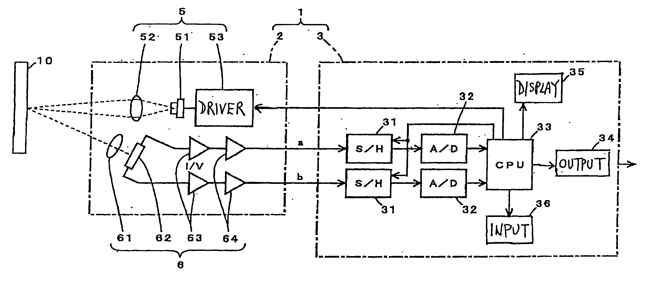
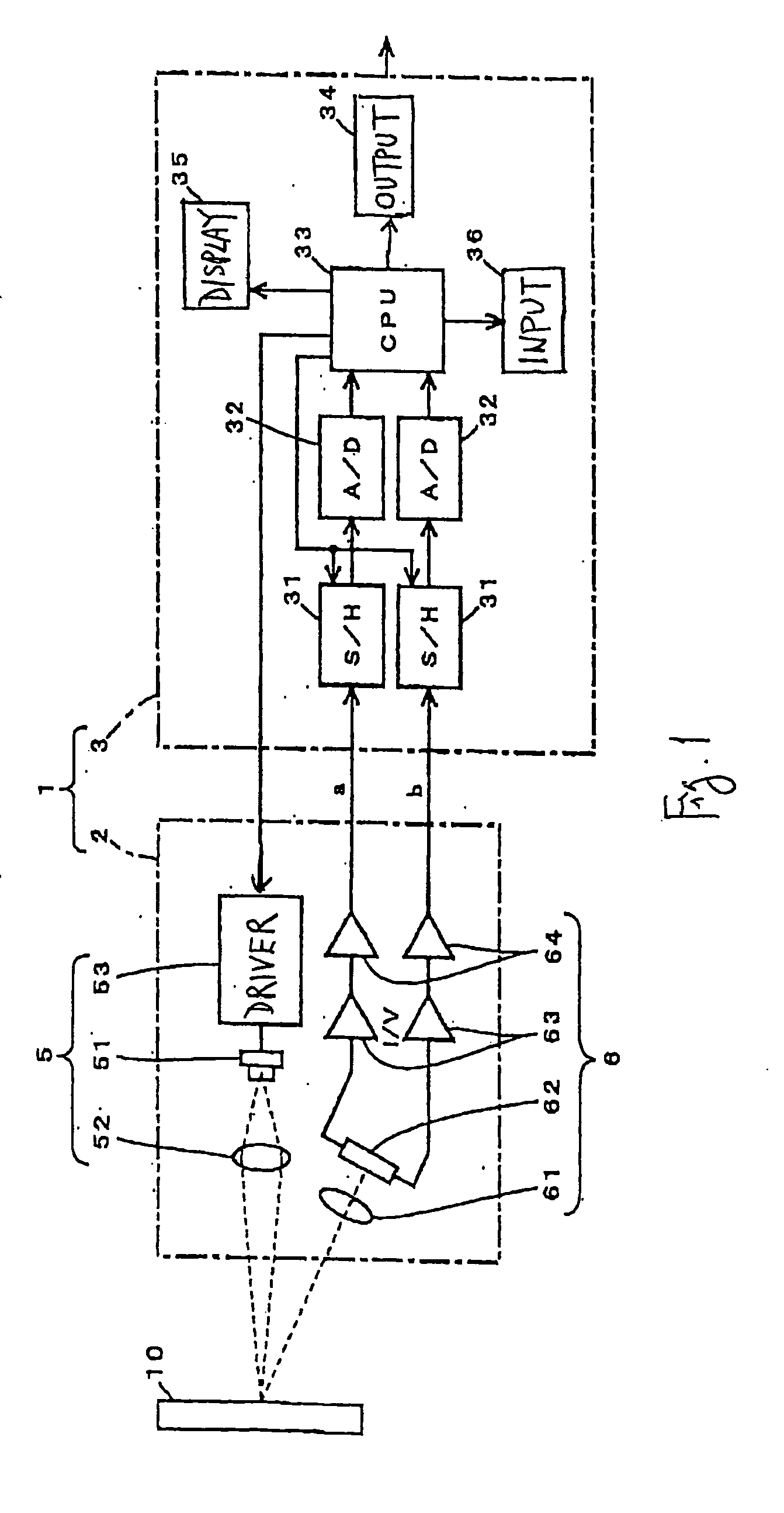
[0028]FIG. 1 shows a displacement sensor 1 embodying this invention, comprising a detector 2 having a light emitter 5 and light receiver 6 incorporated therein and a signal processor 3 for carrying out a series of measurement processes. The detector 2 and the signal processor 3 are separate components and are electrically connected to each other by a cable. The light emitter 5 includes a laser diode 51, a light emission lens 52 and a driver circuit 53 for the laser diode 51. The light receiver 6 includes a light receiving lens 61, a PSD 62 and a pair of current-voltage conversion circuits 63 and a pair of amplifier circuits 64 set individually for two detection signals from the PSD 62.

[0029] The signal processor 3 includes not only a sample-and-hold circuit 31 and an A / D conversion circuit 32 for each of the two detection signals but also a CPU 33, an output circuit 34, a display device 35 and an input device 36. The display device 35 is for displaying results of measurement and th...


PUM


Abstract

An optical reflection sensor emits light and its reflection from a target object is received. A signal processor carries out a measurement on the received reflected light such as the distance to the target object each time the reflected light is received. Repeatability of measured values is calculated and displayed on a display device incorporated into the housing of the sensor. The display device may have two display areas such that the calculated repeatability and the measured value can be displayed simultaneously. The calculated repeatability may be compared with a specified threshold value, with the result of the comparison displayed. The housing may also incorporate an input device through which a required level of accuracy may be set.

Description

BACKGROUND OF THE INVENTION [0001] This invention relates to an optical reflection sensor, or a sensor of the type for receiving light reflected from a target object, processing the received light to make a measurement on the target object and outputting the result of this measurement. [0002] Examples of an optical sensor of this type include distance sensors for measuring the distance to a target object and displacement sensors for measuring displacements on a target surface. Prior art displacement sensors are provided with a light source such as a laser diode and a light receiving element such as a PSD (position sensitive device) and a CCD, emitting and receiving light at a specified timing, extracting the focusing position of reflected light on the light receiving surface of the light receiving element according to the timing of light emission and reception and measuring the distance to the target object by using the focusing position by triangulation. Such a displacement sensor ...

Claims


Application Information

Patent Timeline
Patent Type & Authority Applications(United States)
IPC IPC(8): G01C3/06G01B11/00G01J3/50G01S17/02G01V8/12G02B7/32
CPCG01V8/12G01B11/026
Inventor TOMITA, KOHEIIMAI, KIYOSHINAKASHITA, NAOYAINOUE, HIROYUKI
Owner ORMON CORP
Features
  • R&D
  • Intellectual Property
  • Life Sciences
  • Materials
  • Tech Scout
  • Unparalleled Data Quality
  • Higher Quality Content
  • 60% Fewer Hallucinations
Learn More