Method and system for detecting the disconnection of an auxiliary power suppply from a poly-phase motor

Inactive Publication Date: 2005-11-24
TOYOTA JIDOSHA KK
View PDF3 Cites 34 Cited by
  • Summary
  • Abstract
  • Description
  • Claims
  • Application Information

AI Technical Summary

Benefits of technology

[0021] Still further, according to another aspect of the present invention, ON/OFF of the switching elements of the inverter is controlled based on a gate signal obtained by comparison between a sinusoidal wave voltage command and carrier, so that the sinusoidal wave voltage command is limited to a pre

Problems solved by technology

Because the above-described neutral point voltage of the motor is about one half the voltage on the input side of the inverter, the neutral point voltage is significantly high in typical electric vehicles and hybrid vehicles, which makes it difficult to connect an auxiliary battery to the neutral point in these vehicles.
However, because the neutral point voltage cannot be continuously maintained at a constant value, when the low voltage battery is not available, the voltage to be supplied to the auxiliary equipment changes significantly and constant operation of the equipment is prohibited.
Accordingly, when the low voltage side battery becomes disconnected (namely, electrical connection is interru

Method used


Image

  • Method and system for detecting the disconnection of an auxiliary power suppply from a poly-phase motor
  • Method and system for detecting the disconnection of an auxiliary power suppply from a poly-phase motor
  • Method and system for detecting the disconnection of an auxiliary power suppply from a poly-phase motor

Examples


embodiment 1

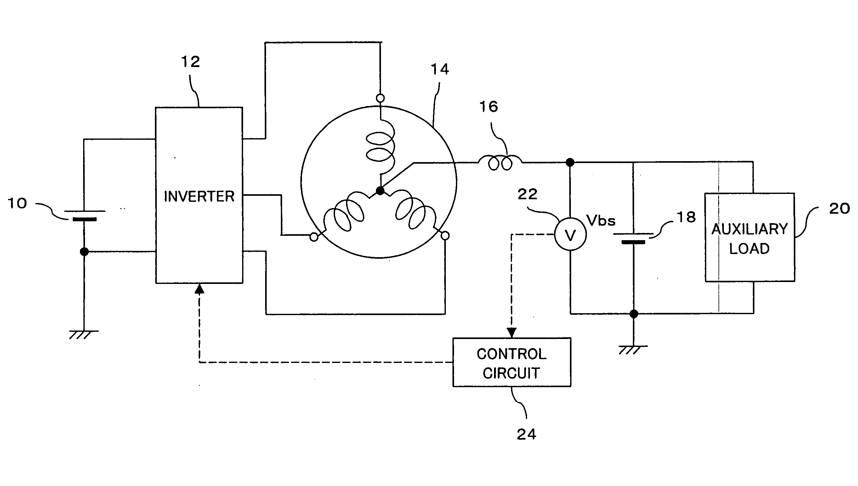
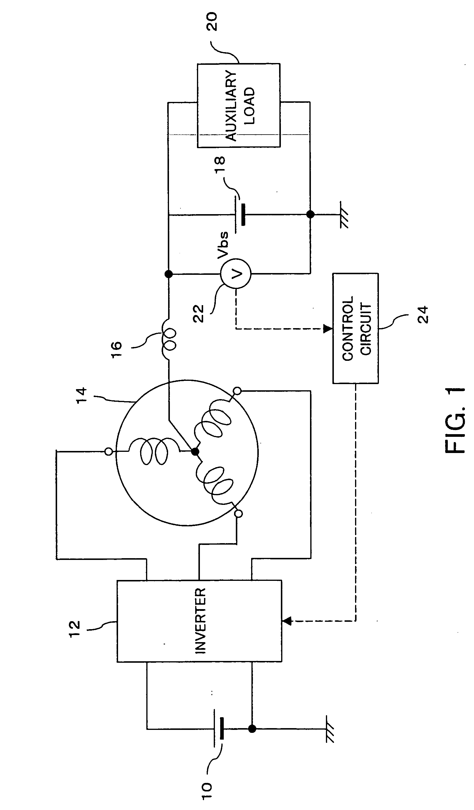
[0043]FIG. 1 shows the overall configuration of an inverter system for driving a poly-phase motor in accordance with an embodiment of the present invention. An inverter 12 is connected to a 36-volt (42V when charged) battery 10 which serves as a main power supply. Namely, a voltage of 36V output from the battery 10 is applied between a positive bus and a negative bus of the inverter 12.

[0044] The inverter 12 has three arms provided in parallel each including two switching elements (transistors) arranged between the positive bus and the negative bus. The inter-transistor points in the respective arms connect respectively to three phase motor output terminals.

[0045] Three phase motor coil terminals of a three-phase alternating current motor 14 are respectively connected to the three phase motor output terminals of the inverter 12. Accordingly, while one of the upper transistors of the inverter 12 is sequentially turned on, a transistor of other arms is sequentially turned on, so tha...

embodiment 2

[0066]FIG. 7 shows a configuration of the system according to a second embodiment of the present invention. In this embodiment, in addition to the voltmeter 22, an ammeter 26 is provided between the auxiliary battery 18 and the power supply line for detecting current of the auxiliary battery 18 (battery current: Ibs). The output from the ammeter 26 is also supplied to the control circuit 24.

[0067] The control circuit 24 measures values related to abnormality, as shown in FIG. 8. Specifically, it is first determined whether or not there is an abnormality in voltage sensing of the power supply line (14V system power supply line) to which the auxiliary battery 18 is connected (S11). This is determined by determining whether or not the output Vbs of the voltmeter 22 has a normal value. For example, when the output voltage Vbs is 8V or less, the various auxiliary loads cannot be driven normally, and abnormality is determined. In particular, when the voltage Vbs is 0V, it is determined a...

embodiment 3

[0095] Referring to FIG. 14, a system configuration in accordance with a third embodiment is shown. In this embodiment, a resolver 28 is provided for detecting a rotation angle of the motor and the output from the resolver 28 is supplied to the control circuit 24.

[0096] As described above, during normal operation, the control circuit 24 controls switching of the inverter 12 based on the output Vbs of the voltmeter 22 to control the current to be supplied to the motor 14, thereby controlling power generation of the motor 14 such that the voltage Vbs becomes a desired value (14V, for example).

[0097] Specifically, it is possible to control the neutral point voltage by changing an on duty ratio between the upper transistor and the lower transistor of the inverter 12. More specifically, when the ON periods are identical for both transistors, the neutral point voltage is equivalent to inverter input voltage (voltage of the battery 10). On the other hand, when the ON period for the upper...


PUM


Abstract

To a neutral point of a motor is connected a positive electrode of an auxiliary battery and an auxiliary load. Voltage on a power supply line to the auxiliary load, a neutral point voltage, is detected, and disconnection of the auxiliary battery is determined when an increase of ripples in the neutral point voltage is detected. When a voltmeter cannot be used, control of the neutral point voltage is continued by measuring current of the auxiliary battery and performing control such that the current value becomes 0. A resolver is further provided on the motor for detecting the rotor angle with high accuracy. A control circuit generates, in accordance with an output of the resolver, a voltage control signal for each phase current having the same amplitude as the carrier amplitude during startup, and compares the voltage control signal to carrier to obtain a gate signal having the same frequency as the carrier frequency. In switching of the inverter, due to this gate signal, periods in which all phases are on or off are reduced, thereby preventing a large neutral point current.

Description

TECHNICAL FIELD [0001] The present invention relates to an inverter system for driving a poly-phase motor comprising an alternating current motor which is driven by an inverter and generates electrical power and a power supply which is connected to a neutral point of the alternating current motor. BACKGROUND ART [0002] Conventionally, alternating current motors have been commonly used as a power source for various devices. In electric vehicles and hybrid vehicles, a system is typically adopted in which direct current supplied from a battery is converted into a desired alternating current by an inverter, and is then supplied to a motor. This system allows a wide range of output torques and also achieves an advantage that electrical power generated by regenerative braking can be utilized for battery charging. [0003] Because a high voltage power supply is effective for a high power motor, electric vehicles and hybrid vehicles usually adopt a high voltage power supply on the order of se...

Claims


Application Information

Patent Timeline
IPC IPC(8): B60L11/00B60L11/18
CPCB60L3/0023B60L11/005B60L11/1803H02P2101/45Y02T10/7005Y02T10/7022Y02T10/642H02P9/102B60L50/40B60L50/51Y02T10/64Y02T10/70
Inventor KUSAKA, YASUSHI
Owner TOYOTA JIDOSHA KK
Why Eureka
Try Eureka